Aligning signals to attain perfect synchronicity.

Clocks are essential gatekeepers of the digital domain. Setting the pace for all that follows the clock can be a single trace or a partnership of two traces that carry complementary signals. Either way, the function of a clock is to switch from high (a logical 1) to low (0) up and down continuously; on, off, on, off, all day long. Signals controlled by the clock switch only when activated by the code, meaning that other signals do not change their state with every cycle of the clock.
An obvious example comes to mind because it interrupts every TV show or conversation that happens in my living room (FIGURE 1). I’ll break it down for you.
Even when no one is home, “Grandma’s clock” rocks one of four tunes every 15 minutes. (Westminster, two “baroque metal” chimes, or the one where the monks took an oath of silence.)
It all runs on a 1Hz gravity-powered system. You could say 500mHz if you count tick and tock separately. That, by the way, is the general principle behind double data rate (DDR) memory.
Of course, the “seconds” hand moves every second. In a quiet room, every tick seems to get a little louder. Isn’t that irritating when you want to sleep? There’s your noise floor in action.
“Tick” and “tock” are not exactly a half-second apart. Perhaps a little phase mismatch? Maybe there’s work and then there’s tock.
The “gravity” is good for a week before someone must pull the three chains that raise the weights. One is as heavy as the other two combined. One “voltage” for the time, one for the song and another for the gong. VBAT!
The sporadic chiming of the hours (gong, gong, gong) and all the other mechanical complications in a tall clock play out over periods of time. The circuit is the same dance with a different song. An endless heartbeat gets to meter whatever event comes next.
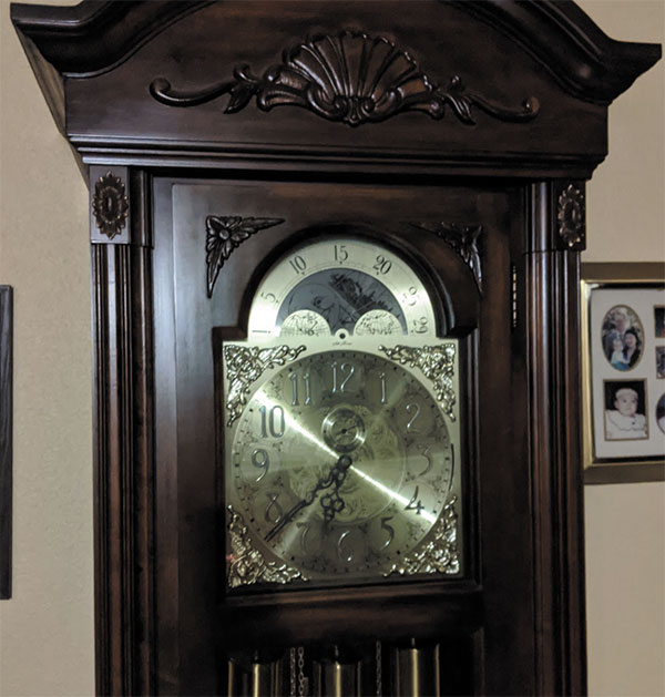
Figure 1. Seconds, minutes, hours and moons in motion.
Noticeable at the top of Figure 1 is the gear reduction (the clockwork that drives the hands) and the lunar cycle rotating on the part that looks like a saw blade. Below is the music box with the pendulum hanging from the center bar at the bottom. Forty-something years ago, this was technology for the home.
Mitigating cross-coupling. Since the clock is the busiest of the bunch, it stands to reason that it would generate a little buzz in the system. That, by itself, is fine and expected. Also expected, but not so fine, is the natural occurrence of cross-coupling, where clock pulses are picked up by a neighboring trace. Giving the noisy trace a little more space helps keep crosstalk to a minimum. Some traces are more susceptible than others to pick up stray oscillations from a clock signal. If the clock is a bad neighbor, then increasing the air gap around the trace is desirable.
Every design will have a victim/aggressor dynamic. Some will have lots of potential encounters. Be aware of this in a simple design, and document it in a medium or larger design. In this case, “document” refers to the constraint manager and the ability to select certain types of nets and apply as many rules as it takes to define the system’s acceptable parameters.
A clock would be worthless without some companions. Data are usually a good bet to follow a clock. All the acronyms are at your disposal: PCIe, WiFi, SPI, MIPI and USB to name a few; all have their own clock. They vary in terms of edge rates and how finely the group should be matched in length, if at all. You will have to find that out for yourself. The easiest way is to do it right the first time, so it helps to learn what you can about whatever bus you are, ahem, driving.
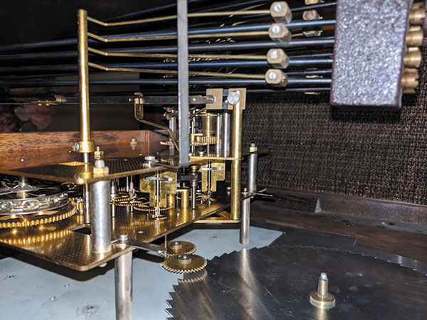
Figure 2. The gong quartet of hammers, ready to strike.
DDR memory impact on system design. This is great stuff because it allows a 2X increase in DRAM (volatile memory) performance without doubling the clock rate. Breakthroughs don’t come along every day. We need advancement in technology of this magnitude every other year or so to keep the whole thing going. Using the rising and falling edge of the clock’s pulses to sweep the memory registers more efficiently, so it is here to stay, for now.
Routing DDR (pick a number) comes down to knowing which data lines are associated with a given clock and which address lines go with a particular strobe. Bypass capacitors are vital in terms of their placement. When all the registers slam to zero, it’s the caps that pour out a surge of voltage in that instant. They keep the system from freezing up. This is probably truer with mobile devices where power is at a premium.
External oscillators. Crystals are a standard part of a typical microcontroller with anything wireless. Even when there is an on-board clock, the ability to have options is provided for better devices. There are set-value crystals, and others with a bit of variability on hand called VCXOs. It is natural for the frequency of a crystal to change over temperature. TCXO, or temperature compensated crystals, have built-in compensation circuitry to keep them on track. Another type is an OCXO, or oven-controlled external oscillator, which is a level above the TCXO in terms of linearity at higher temperatures.

Figure 3. Some busses have many members; others, not so much.
Implementing crystals is usually straightforward. They are placed next to the XO pins of the device and routed through a couple of passive components with short lines. When the layout does not afford a nearby placement, take extra care to create a guardrail around the traces between the crystal and the IC it is driving. If you happen to flood the outer layer with ground pour (and you probably should), a slot around the three exposed edges of the crystal will help prevent noise from going where it should not go.
The crystals ring at a fundamental tone, 10 to 20MHz perhaps, and there will be peaks on the spectrum from harmonics of the fundamental frequency. This kind of electromagnetic radiation can cause a product to fail FCC tests for noise emission and immunity. Anything other than an ideal layout for the oscillator(s) should be tightly engineered to contain EMI.
Timing budgets. The timing budget narrows with the number of conductors in the data bus. Keeping impedance mismatches to a minimum and giving the CLK nets high priority when it comes to routing obstacles are basic requirements. Shielding sensitive lines away from the all-night party is a step in the right direction. Aligning the signals so everything happens with perfect synchronicity is the fun and rewarding part. Getting done on time? That is also up to you. •
John Burkhert Jr. is a career PCB designer experienced in military, telecom, consumer hardware and, lately, the automotive industry. Originally, he was an RF specialist but is compelled to flip the bit now and then to fill the need for high-speed digital design. He enjoys playing bass and racing bikes when he’s not writing about or performing PCB layout. His column is produced by Cadence Design Systems and runs monthly.


