Fredrick Grover’s invaluable tome is essential for partial inductance calculations.
Inductance is probably the most confusing topic in signal integrity, yet one of the most important. It plays a significant role in reflection noise, ground bounce, PDN noise and EMI. Fortunately, the definitive book on inductance, originally published in 1946 by Fredrick Grover, is available again.
After two printings in the 1940s, Grover’s Inductance Calculations was out of print by the mid 1980s. It was just reprinted this year and is available from Amazon in paperback (amazon.com/Inductance-Calculations-Dover-Books-Engineering/dp/0486474402/ref=sr_1_1?ie=UTF8&s=books&qid=1260191720&sr=8-1) for a very low price.
Motors, generators and RF components experienced a period of high growth in the 1940s. At their core were inductors, and being able to calculate their self- and mutual-inductance using pencil and paper was critical. (Keep in mind this predated the use of electronic calculators.) While many coil geometries had empirical formulas specific to their special conditions, Grover took on the task of developing a framework of calculations that could be applied to all general shapes and sizes of coils.
While Grover does not explicitly use the term, what he calculates in his book are really partial inductances, rather than loop inductances. A raging debate in the industry today is about the value of this concept. Proponents say it dramatically simplifies solving real-world problems and is perfectly valid as a mathematical construct. You just have to be careful translating partial inductances into loop inductances when applying the concept to calculate induced voltages. Opponents say there is no such thing as partial inductance; it’s all about loop inductance, and if you can’t measure it, you should not use the concept. There is too much danger of misapplying the term.
I personally am a big fan of partial inductance, and use it extensively in my book, Signal and Power Integrity – Simplified. It eases understanding the concepts of inductance, and highlights the three physical design terms that reduce the loop inductance of a signal-return path: wider conductors, shorter conductors, and bringing the signal and return conductors closer together. Most important, partial inductance is a powerful concept to aid in calculating inductance for arbitrary shaped conductors.
Inductance is fundamentally the number of rings of magnetic field lines around a conductor, per amp of current through it. In this respect, it is a measure of the efficiency for which a conductor will generate rings of magnetic field lines. To calculate the inductance of a conductor, it is a matter of counting the number of rings of field lines and dividing this by the current through the conductor. Counting all the rings surrounding a conductor is really performing an integral of the magnetic field density on one side of the conductor.
Literally everything about the electrical effects of interconnects stems from Maxwell’s equations. Grover starts from the basic Biot-Savart Law, which comes from Ampere’s Law and Gauss’s Law, each, one of Maxwell’s equations, and derives all his approximations. The Biot-Savart Law describes the magnetic field at a point in space from a tiny current element.
Using this approach, Grover is able to calculate the magnetic field distribution around a wide variety of conductor geometries and integrate the field (count the field lines) to get the total number of rings per amp of current. Using clever techniques of calculus, he is able to derive analytical approximations for many of these geometries.
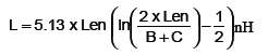
The most commonly used approximation is for the partial self-inductance of a long, straight rectangular conductor, such as a lead frame in a QFN package or a connector pin. He calculates it as:
where L = the partial self-inductance in nH B, C are the thickness and width of the conductor cross section in inches Len = the length of the conductor in inches.
For example, for a 1˝ long lead, 0.003˝ thick and 0.010˝ wide, the partial self-inductance is 23 nH. This is roughly 25 nH per inch, or 1 nH/mm, which is a common rule of thumb for the partial self-inductance of a wire.
If you deal with connectors, packages, vias, board discontinuities or odd-shaped transmission lines, and need to estimate the loop inductances of non-uniform sections, Grover’s book is a great resource. You will have a great collection of inductance approximations at your fingertips. It is well worth the low price.
Dr. Eric Bogatin is a signal integrity evangelist with Bogatin Enterprises, and has authored six books on signal integrity and interconnect design, including Signal and Power Integrity – Simplified, published in 2009.
Offshoring works best for stable designs and predictable demand.
“We need to try to bring the price down some more,” the customer told me over the phone.
It was 2005 and the company I worked for was a custom OEM primarily serving the telecommunications industry. After the telecom collapse, everyone wanted the lowest cost possible, and no one was able to forecast sales beyond three months. Long-term purchase orders that helped with downstream planning were a thing of the past. We already had squeezed the supply chain as much as we could; without longer-term planning, I was unable to get additional volume discounts on material. The customer was a startup, though, and was attempting to hit a price point that it was sure would sell decent volume. We were looking at around 2,000 pieces per year, which for us was high volume.
After management review, we decided to attempt to outsource the board for cost savings. I had some experience with Chinese manufacturing, and our company was in the process of setting up an office in India with an eye toward offshoring certain engineering operations and assembly. The thinking was, by having our own office in a low-cost country, we would be able to better manage the offshore suppliers. I sent RFQs to China and to our Indian office. Even at the lower volume, I was able to find cost savings: 35% in China and 25% in India. For various reasons, the Indian supplier was selected, and the customer was happy with the cost savings. Now it fell to me to manage the supplier.
I had heard the horror stories associated with offshore sourcing, mostly related to product quality. I had one customer that set up a closed-circuit camera in one of its offshore partners’ facilities. When boards were completed, the manufacturer (in India) placed the finished product on a table under the camera. The US customer logged into the camera and inspected the boards remotely before permitting shipments. This situation seemed overly involved to me, and was one I was determined to avoid. Worldwide shipping services had largely eliminated cost concerns I had previously heard about in early offshoring discussions. I no longer needed to wait for a container to be full to get product shipped at an acceptable cost. Sure, it was more expensive than my local supplier delivering the boards, but that cost adder had been factored in my sell price to my customer. I also had been warned of language barriers and time zone delays as potential issues. I found the majority of my contacts in India spoke English nearly as well as I did – accented English, to be sure, but still very understandable. The Indian companies we did business with had also set their mid- and upper-level management personnel on second shift. This allowed them to work with our normal first-shift hours in the Eastern time zone. We also had local representatives who could be sent to the manufacturing facility to oversee our needs.
Initially, the relationship worked rather well, despite my reservations and fears. As time elapsed, however, we began to run into issues, primarily with on-time delivery. The supplier was unable to efficiently adjust to our needs, based on either material availability in country, or assembly capacity. We needed releases of 200 pieces, but they would run 500 at a time. Units would fail test, and instead of asking for help troubleshooting, they would push them aside in favor of other customer demands. We’d make engineering changes, and they would neglect to update their assembly documentation, or make us take previous revision boards due to their overruns. We had never discussed minimum lot quantities, nor were they a condition of the contract. The supplier also purchased material at much higher quantities than needed for the orders we had placed, and then asked us to cover the material overage costs, another item that was not a condition of its quote, the contract or our purchase order.
Most issues we encountered were similar to issues encountered with local suppliers, but were aggravated by the distance. I was unable to effectively manage the issues with the time zones involved while maintaining adequate lead times. The stateside overhead required to manage the product was not factored into a landed cost analysis of the product, and quickly absorbed any cost savings. In the end, we were forced to bring the product back onshore so that it could be efficiently produced and managed.
As with all outsource evolutions, planning is essential to successful offshoring. If the design is not stable, or demand not relatively predictable, the odds of success decrease. Stateside management costs must be factored into the landed costs, more so with volatile demand products. I believe offshoring could be an effective solution for the right product and volume mix. However, offshoring is not a viable option when demand is variable and the design is not stable. Stick with a flexible onshore supplier for these sorts of products.
Time and technology passes, but the three drivers of change remain static.
It really wasn’t until a couple of weeks ago that it hit me: We are no longer in the first decade of the “new millennium.” Remember Y2K? Well, that was 10 years ago – eons in the world of electronic technology.
Scarier still is looking back at what the pundits were predicting on the eve of Y2K. Some saw gloom and doom for the modern world because of old analog clocks, unable to handle moving from “19” to “20,” therefore shutting down our modern utility-driven world. Others saw the fortunes of Wall Street moving ever onward and upward with another 250% gain for the decade. Some in our industry saw the size, profitability and clout of the North American printed circuit board industry leading the world, while other global areas continued to try to catch up. Let’s see: wrong, very wrong and sorta wrong. So much for pundits.
As much as some things have changed, the drivers of that change remain amazingly consistent with the drivers of all changes since anyone can remember or history has documented. No matter how tantalizing or technologically sophisticated the future appears to be, basics still govern. Over the years, when I have asked the “older and wiser’ among us – those who have helped us get to where we are today – the three drivers cited have been the same as those mentioned by young up-and-coming technologists, those leading us into the future. As I try to adjust to the second decade of the new millennium, I find myself considering how ageless and powerful these can be.
Curiosity is the driver that makes us ask questions. Without asking questions, such as how does this work, or what can I do to improve something, momentum never changes. In our industry, designers are perhaps the best example of those who always ask questions and consider the corresponding thoughts of “what if?” But curiosity is not limited to those who design product. Many a sale has been made by those curious about what other companies might need. Equally, in manufacturing no improvement can take place without someone asking how a process can be improved.
Ideas includes devising answers to the questions that curiosity causes. Initiating change comes not from accepting the status quo, but from developing ideas about what to do next. Again, designers do this all the time and seemingly effortlessly with tremendous results. Salespeople also come up with ideas that transform an unapproachable prospect into a loyal customer. Ideas transform the status quo into the “what if?”
Effort is the catalyst that enables curiosity to lead to an idea and that idea to be transformed into a result. Effort requires far less imagination or intelligence, but without it, nothing will result. Effort is the sweat it takes to work through the details and turn an idea into a satisfactory solution to the question initiated by curiosity.
Which brings me back to the pundits and their predictions. Despite those pesky analog clocks, the world did not end, because someone became curious and determined there was a problem. Then someone came up with ideas that might resolve the problem. We all took part in the effort to replace the disruptive clocks and controllers with digital versions, thus averting the Y2K gloom and doom.
Wall Street, on the other hand, was far less curious, had no idea, and therefore made no effort. By assuming something might happen and being comfortable with the status quo, just about every metric this past decade has been lost insofar as asset growth and wealth generation. Most investors have at best tread water, in large part because of complacency and an aversion to taking advantage of drivers that cause change.
Closer to home, our industry has experienced much change – some good, some not. Technology has marched forward because people remain curious, come up with great ideas and make the effort to convert ideas to cutting-edge product. Make no mistake, it is not software that enables technological advances, but rather the people who continually ask questions and challenge the norms – and then do something about it.
But for some, it has been a different story. Too many became complacent at the end of the 1990s. The curiosity to imagine what might be, and consider how best to make it happen, seemed to fade into the status quo. For others, many in far-flung parts of the world, curiosity was rampant. Ideas flowed like water. The effort was made to harness those ideas to satisfy the curiosity, and in 10 short years the epicenter of much of the technological world has shifted to places some thought unimaginable.
One of the many lessons of the past decade we all can apply to this new one is that if you become too complacent, the world will pass you by and in the worst way. Equally, if you stick to your knitting and be proactively curious, creatively developing new ideas and making the effort to take full advantage of that curiosity and thought, life can be good. The trick is making sure that everyone – from the top of the organization through all lower levels – doesn’t become complacent, but instead keeps thinking “what if?” That’s what good leadership inspires.
We in the technology world need to remember that every day offers us (and our competition) time for dynamic change to take place. Those who are getting ahead may be doing so by simply being curious, encouraging ideas and then making the effort – as daunting as it may seem at times. The challenge – and opportunity – is to remember to be curious, to have ideas, and to make the effort.
Peter Bigelow is president and CEO of IMI (imipcb.com); This email address is being protected from spambots. You need JavaScript enabled to view it.. His column appears monthly.
Macroeconomic cycles are real, but are they reliable indicators of EMS growth?
Perhaps the industry’s most frustrating aspect is its cyclical nature. Equipment manufacturers and OEMs cannot escape the desperate ups and downs. While there are natural cycles of consumption and excess, they usually are the result of consumer spending variations that thread through the supply chain and create havoc with the supplier base.
Worst hit are equipment suppliers, whipped by the combination of end-user demand and OEM whims concerning predicted fulfillment. The chain reaction of supply makes this boom/bust scenario chaotic and excessive in terms of forecasting revenue. It is often an accumulative effect in which the tail of the chain – the equipment/manufacturing guys – gets whacked most, while distributors and EMS suppliers are left with excess or deficient inventory.
This is all specific to product industries – PCs, notebooks, LCD monitors/TVs, set-top boxes and video console games, to mention a few. To be sure, OEMs are their own worst enemies – they hedge against upside demand and over-predict against downside supply – to their, and their suppliers’, misfortune. Yet, who cannot claim to be accurate and wise after the fact? As a forecaster, I can honestly say that when we are spot-on, it is sheer luck, and when we are wildly off, we hide until the storm passes.
One hopes time will provide wisdom and sanity. We try to integrate knowledge gained from watching such cycles in our current forecasts. Conservatism seems to pay dividends, yet we have often been wrong. Sometimes we have been astoundingly accurate – shockingly – yet we know that we must attribute it to luck.
A few examples make this point. In 2000, when the market was booming, we precisely predicted EMS market growth, but this was because it was exploding and there seemed no end in sight. When the downturn arrived, it was very embarrassing to revise our forecasts. Similarly, we expected a solid 2009. We lick our wounds and beg for forgiveness and forgetfulness.
Yet, who could know? Cycles exist that seem beyond our awareness. The Foundation for the Study of Cycles (foundationforthestudyofcycles.org) is well aware of this, if you believe in such things as planetary or cosmic/organic cycle studies. It is a fascinating organization, one that examines not just economic cycles, but other systemic movements in nature and life that seem to follow patterns outside our predictive natures. I can’t say that I agree with all its predictions, but I am interested insofar as they help us understand our businesses.
Edward R. Dewey, a Harvard economist and founder of the FSC, made this bold statement: “Cycles are meaningful, and all science that has been developed in the absence of cycle knowledge is inadequate and partial. [A]ny theory of economics, sociology, history, medicine, or climatology that ignores non-chance rhythms is as manifestly incomplete as medicine was before the discovery of germs.”
Cyclic prizes that have been awarded for observing solar and lunar cycles such as El Niño correspond to droughts in Northeastern Brazil, Morocco and the American Southwest, specific markets, economics, and forecast turning points in international business cycles, with some even going so far as to predict the systematic cycles of war, tree ring widths, weather, biophysical science, civil violence, insurance, motivation and yes, corporate lifecycles! It all can become a little esoteric when it comes down to biocybernetics and new option markets, but so it goes.
Back on earth, cycles both exist and (seem to) recur. Electronics seems to be an industry of boom and bust, much to its participants’ consternation. Yet, growth endures and every year we look forward to new gains. In this regard, I can positively predict the EMS and electronics assembly industries and their corollaries will continue to grow, albeit at varying rates. The recession cycles are the most disturbing and unpredictable.
I am not advocating cyclic studies to help us understand the economics of electronics manufacturing; they should be considered in the larger context.
Macroeconomic cycles are real, despite our subtle denial. I wish we were able to harness them better in our work. In the meantime, we will try our best to work with our best knowledge, intellect and intuition to help our clients predict future product demand. Otherwise, suppliers must rely on their own intelligence, and where does that come from? Is it best guess, economic indicators, prognosticators, cyclic studies? We would be silly to promote such a view as cyclic studies; however, it introduces a fascinating dimension to a world that has not been completely proven.
We left off last month pontificating on the so-called “conflict metals” – ores mined in the Democratic Republic of Congo, often by child laborers under duress and whose efforts inadvertently underwrite the now decade-long war that has led to the slaughter of millions and devastated that African nation.
Various world bodies, including the US government, are considering legislation to force buyers away from these contested metals. Sounds good on paper, but the issue remains that refined metals are indistinguishable, with no identifying thumbprint. Solder suppliers purchase the metals on exchanges, far too late for any traceability.
Several stakeholders have latched onto to this problem – which is good. There are potential rubs, but the recent discussions suggest progress in the right direction. To bring readers up to date, on Dec. 9, 13 representatives from various industry trade groups and electronics companies met in Paris to discuss potential outcomes. Among those attending the meeting were representatives of Intel and Motorola. As if to underscore the weight of the matter, per the meeting minutes, the two companies agreed conflict mining is unacceptable, with Intel saying a solution would be necessary within six months.
Via a joint workgroup of the EICC (Electronics Industry Citizenship Coalition) and GeSI (Global e-Sustainability Initiative) – the former a group of large electronics companies, the latter a nonprofit association – Intel, Motorola and their corporate colleagues are collaborating with experts, governmental and non-government bodies, academia, and other supply-chain organizations to “learn more about mineral mining and processing.”
Last seen in these parts dissuading lead use, the International Tin Research Institute last July hatched a three-phase plan (the Tin Supply Chain Initiative, or iTSCi) to ensure due diligence through written documentation by traders and comptoirs. Such evidence would prove legal status, legitimacy, export authority and certificate of origin. ITRI, whose members are the world’s big tin miners and smelters, requires the documentation on every shipment and claims “most players now recognize the need for improvement.”
More critical is Phase 2 of the iTSCi: traceability to the mine. The plan calls for achieving this through a system of unique reference numbers assigned to each parcel of material shipped from the mine site. Information on the reference number would be recorded on paper as minerals are moved. The final document, which records for audit purposes the unique reference numbers issued at the preceding point in the supply chain, is a Comptiors Provenance Certificate, and would become a precondition for any export of mineral to ITRI member smelters.
The process, ITRI says, should ensure any export shipment leaving DRC could be tracked back, via the tag number, to the mine/area where it was produced, and provide confirmation that the mine or source area, transport routes, and all the middlemen in the chain are “clean.” (For more information on the first two phases, see itri.co.uk/pooled/articles/bf_partart/view.asp?q=bf_partart_310250.)
When millions are dying, all solutions must be considered. I like that the industry is taking charge here, as opposed to leaving its fate to governments that might be prone to legislating a “solution” without necessarily understanding (or caring about) the technical and logistical hurdles. I have been a skeptic of the validity of audits, and remain somewhat unconvinced the methodology put forth will be sufficient and uncorrupted. But it’s coming together much better – and faster – than I could have hoped, and all those involved deserve considerable credit.
Virtual world. Early next month, the 3d Annual Virtual PCB trade show takes place. As we went to press, two major CAD software companies, EMA and Altium, had just signed on, as had placement and screen printer equipment OEM Assembléon. Moreover, UP Media signed a deal under which SMTA has been made an exclusive partner, and will support the show with brand new technical Webinars and other programming. We are thrilled with the turnout of the past two shows – a total of 4,800 registrants – and excited at the prospects going forward. Register now at virtual-pcb.com. It’s free, and you never have to leave your desk.
Tweet, tweet. And for the latest news alerts, don’t forget to follow us on Facebook and Twitter (http://www.twitter.com/mikebuetow).
Boundary scan’s low-cost and IC level access has pushed its use beyond traditional board test applications.
Boundary scan is a method for testing interconnects on PCBs or sub-blocks inside an integrated circuit. It has rapidly become the technology of choice for building reliable high technology electronic products with a high degree of testability.
Boundary scan, as defined by IEEE Std. 1149.1 developed by the Joint Test Action Group (JTAG), is an integrated method for testing interconnects on PCBs that are implemented at the IC level. The inability to test highly complex and dense printed circuit boards using traditional in-circuit testers and bed-of-nails fixtures was evident in the mid 1980s. Due to physical space constraints and loss of physical access to fine pitch components and BGA devices, fixturing cost increased dramatically, while fixture reliability decreased at the same time.
The boundary scan architecture provides a means to test interconnects and clusters of logic, memories, etc., without using physical test probes. It adds one or more so-called “test cells” connected to each pin of the device that can selectively override the functionality of that pin. These cells can be programmed via the JTAG scan chain to drive a signal onto a pin and across an individual trace on the board. The cell at the destination of the board trace can then be programmed to read the value at the pin, verifying the board trace properly connects the two pins. If the trace is shorted to another signal or if the trace has been cut, the correct signal value will not show up at the destination pin, and the board will be known to have a fault.
When performing boundary scan inside ICs, cells are added between logical design blocks to be able to control them in the same manner as if they were physically independent circuits. For normal operation, the added boundary scan latch cells are set so they have no effect on the circuit, and are therefore effectively invisible. However, when the circuit is set into a test mode, the latches enable a data stream to be passed from one latch to the next. Once the complete data word has been passed into the circuit under test, it can be latched into place. Since the cells can be used to force data into the board, they can set up test conditions. The relevant states can then be fed back into the test system by clocking the data word back so that it can be analyzed.
The principles of interconnect test using boundary scan are illustrated in Figure 1, depicting two boundary scan-compliant devices, U1 and U2, which are connected with four nets. U1 includes four outputs that are driving the four inputs of U2 with various values. In this case, we will assume the circuit includes two faults: a short between Nets 2 and 3, and an open on Net 4. We will also assume a short between two nets behaves as a wired-AND, and an open is sensed as logic 1. To detect and isolate the above defects, the tester is shifting the patterns shown in Figure 1 into the U1 boundary scan register and applying these patterns to the inputs of U2. The input values of U2 boundary scan register are shifted out and compared to the expected results. In this case, the results (marked in red) on Nets 2, 3, and 4 do not match the expected values and, therefore, the tester detects the faults on Nets 2, 3 and 4.
By adopting this technique, it is possible for a test system to gain test access to a board. As most of today’s boards are very densely populated with components and traces, it is very difficult for test systems to access the relevant areas of the board to enable them to test the board. Boundary scan makes this possible.
Debugging. While it is obvious that boundary scan-based testing can be used in the production phase of a product, new developments and applications of IEEE-1149.1 have enabled the use of boundary scan in many other product lifecycle phases. Specifically, boundary scan technology is now applied to product design, prototype debugging and field service.
A large proportion of high-end embedded systems has a JTAG port. ARM [Advanced RISC (reduced instruction set computer) Machine] processors come with JTAG support, as do most FPGAs (field-programmable gate arrays). Modern 8- and 16-bit microcontroller chips, such as Atmel AVR and TI MSP430 chips, rely on JTAG to support in-circuit debugging and firmware reprogramming (except on the very smallest chips, which don’t have enough pins to spare and thus rely on proprietary single-wire programming interfaces).
The PCI (Peripheral Component Interconnect) bus connector standard contains optional JTAG signals on pins 1 to 5; PCI-Express contains JTAG signals on pins 5 to 9. A special JTAG card can be used to re-flash corrupted BIOS (Basic Input/Output System). In addition, almost all complex programmable logic device (CPLD) and FPGA manufacturers, such as Altera, Lattice and Xilinx, have incorporated boundary scan logic into their components, including additional circuitry that uses the boundary scan four-wire JTAG interface to program their devices in-system.
ACI Technologies Inc. (aciusa.org) is a scientific research corporation dedicated to the advancement of electronics manufacturing processes and materials for the Department of Defense and industry. This column appears monthly.