The properties of inductance are confusing because of how they are described, not because inductance requires a lot of integrals to calculate.
Inductance is confusing to most engineers, but it’s not your fault; it’s because of what we are taught about it in school. Look in any physics, electrical engineering or electromagnetics textbook under inductance, and you will see one of two explanations. It either describes inductance as “flux linkages through coils” or in terms of the integral of the magnetic flux density across an area.
While both of these explanations are perfectly correct, they don’t help a non-PhD understand enough about inductance to solve any useful problems. Where are the coils in a circuit board trace? And what intuition do we gain from taking the integral of the flux density?
A popular description of inductance is that it is related to the energy stored in the magnetic field around a conductor. While this is partially true, in that the energy in the magnetic field is due to the inductance of the conductor, the energy in the field is also about how much current is in the conductor. Even so, how do we use this information to help us understand what inductance is and influence how we design interconnects?
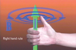
Inductance can be simply understood by thinking about the magnetic field lines around a current flowing through a conductor. When a current flows in any conductor, like a simple wire, there will be circular rings of magnetic field lines around the wire that act as though they endlessly spin around and around the conductor.
The Right-Hand Rule describes the direction in which the rings circulate. Point the thumb of your right hand in the direction of the current and your fingers curl in the direction the rings circulate.
|

FIGURE 1. Rings of magnetic field lines circulate around a current based on the Right Hand Rule.
|
While the energy in the field is about the total number of rings of magnetic field lines around the conductor, inductance is not about the absolute number of rings. If we double the current, we double the number of rings of magnetic field lines but we don’t change the inductance of the wire. Rather, inductance is a measure of the efficiency of the conductor to create rings of magnetic field lines, at the price of the current through the conductor.
This is very similar to capacitance. Capacitance is a measure of the capacity of a pair of conductors to store charge at the price of the voltage between the conductors. The higher the capacity to store charge, the more charge can be stored for the same voltage between the conductors. Capacitance is a measure of the efficiency of storing charge, at the price of voltage.
The efficiency of storing charge does not depend on the absolute amount of charge that is currently on the conductors, it is just about the geometry of the conductors and the material properties. Bring two conductors closer, and the amount of charge they can store per volt between them increases. A wide signal trace microstrip has a greater efficiency of storing charge than a narrow conductor microstrip, and it has a higher capacitance. This is true if there is no voltage on the signal line or if there is 1 kV on the signal line.
Likewise, inductance is a measure of the efficiency of a conductor path to create rings of magnetic field lines, and the price you pay is the current through the conductor. You don’t need current in the conductor to have an efficiency of creating rings of magnetic field lines.
Here is where the properties of inductance get confusing: It’s not because inductance requires a lot of integrals to calculate; it’s because of the words we use to describe it.
No current can exist in the real world as a single isolated length of current. All currents must flow in a continuous loop, from a source and back to the source. Any current we see in a section of a conductor is always going to be part of a complete current loop. Further, we can have more than one current path producing rings of magnetic field lines. Some of the rings from one current loop can overlap adjacent current loops. We have to have a way of unambiguously describing from which part of the current path we are counting the rings of magnetic field lines, and from which current those rings came.
We use the terms “loop” and “partial” to describe the amount of the loop about which we are counting the rings of field lines, and the terms “self” and “mutual” to refer to where the current is that gave rise to those specific rings. This gives a combination of four different kinds of inductances. There is the loop self-inductance, the loop mutual inductance, the partial self-inductance and the partial mutual inductance. Each has an important and distinct role to play in signal integrity applications. PCD&M
Dr. Eric Bogatin is president of Bogatin Enterprises. This and other topics are covered in the public classes Eric teaches. Check his web site for the schedule: BeTheSignal.com. Send questions to This email address is being protected from spambots. You need JavaScript enabled to view it..


