
In-pair skew and rise/fall time mismatch can impact EMC performance.
The use of so-called differential signaling for high-speed signals has become very common in today’s high-speed system designs. While this signal strategy allows better data quality and signal integrity at the receive end of the PCB traces and/or cables, there are some significant EMC and signal integrity issues that are not readily apparent. This discussion demonstrates that significant amounts of common-mode signals can be created when the differential signals have small amounts of in-pair skew or if the rise/fall times are slightly different. These common-mode signals can have a significant impact on the EMC performance, causing significant levels of emissions unless careful design consideration is given to common-mode current return (ground return).
Many differential signal drivers in today’s high-speed system designs actually use a pair of complementary single-ended drivers (once the actual drivers are analyzed in the driving IC). That is, both traces are driven out-of-phase with respect to the PCB ground-reference. For this reason, we call these nets “pseudo-differential.” At the receive end, the ASIC is usually a true differential receiver, which only looks for the difference between the two nets, without reference to the PCB ground-reference plane. In this way, the complementary single-ended nets become differential at the receiver. Since the receiver is only measuring the difference between the two nets, any common-mode signals (signals that exist on both nets at the same time and in phase) are ignored by the receiver. This provides additional signal quality and allows longer traces to be used for higher data rates than the traditional single-ended nets since much of the incident noise is coupled equally to both legs of the differential pair. Even if true differential drivers are used, small amounts of path length difference within the IC or on the PCB will cause significant in-pair skew, and slight differences with the IC will cause some rise/fall time mismatch.
From an EMC perspective, the common-mode signals on these traces and cables can cause the same problems as any single-ended trace/cable. In fact, common-mode signals cause these traces and cables to be equivalent to high-speed, single-ended nets from the EMI/EMC point of view.
Effects of Skew
An example pseudo-differential signal of 1 Gb/s (500 psec. pulse width) with a nominal rise/fall time of 95 psec. was created using a spreadsheet program. The second output of the complementary driver was delayed, introducing skew from two to 60 psec. This skew represents a skew of 0.4% to 12% of the pulse width. The resulting voltage waveforms are shown in Figure 1.
|
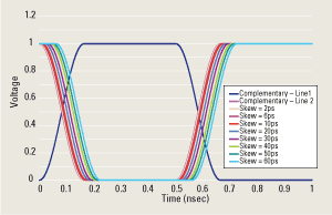
FIGURE 1. Pseudo-differential voltage pulses with skew.
|
The resulting differential pulse at the receiver is created by subtracting the two signals and is shown in Figure 2. Note that while the differential pulse shows some distortion from the skew of the original two complementary single-ended signals, the final differential pulse is acceptable even with large amounts of skew.
|
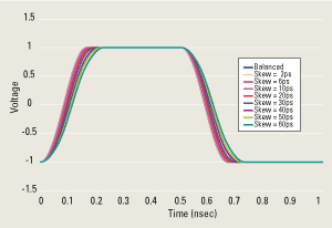
FIGURE 2. Differential voltage pulse shape shape with skew of 1Gbit/sec and 95 psec rise/fall time.
|
Figure 3 shows the common-mode voltage for the various amounts of skew. The common-mode voltage was found by adding the two signals for every instant in time. As the skew increases, the amplitude of the common-mode voltage increases.
|
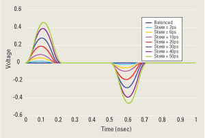
FIGURE 3. Skew-induced common-mode voltage from differential voltage pulse.
|
Effects of Rise/Fall Time Mismatch
The previous section showed how rapidly the skew of the pseudo-differential signals can cause common-mode voltage. This section examines the effect of rise and fall time mismatch between the two complementary signals. Figure 4 shows the complementary voltage pulses with the rise and fall times varied from 80 psec. to 115 psec. The resulting common-mode voltage is shown in Figure 5.
|
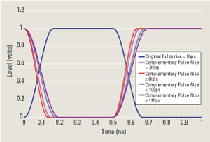
FIGURE 4. Voltage pulses with rise/fall time mismatch.
|
|
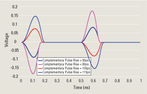
FIGURE 5. Common mode voltage from rise/fall time mismatch.
|
Significant common-mode voltage was created with relatively minor (and typical) rise/fall time mismatch. While not as large as the common-mode signals caused by skew, the real-world signals will combine both causes and the resulting total common-mode noise signal will be the source for EMI emissions.
Summary
Designers often believe that differential signals will not impact the EMI/EMC performance of their designs. This is only true if the two signals are exactly balanced. However, it is impossible to achieve this perfect balance. Thus, there is always some amount of in-pair skew and/or rise/fall time mismatch. The in-pair skew need only be a small percentage of the pulse width before significant common-mode signals are created. These common-mode signals act exactly as single-ended signals, with return currents in the adjacent plane, and with all the EMI/EMC concerns of normal single-ended nets. In addition, high-speed differential signals are often passed through external cables with no shielding (or limited shielding), and the common-mode signals cause significant emissions. PCD&M
Dr. Bruce Archambeault is an IBM distinguished engineer at IBM in Research Triangle Park, NC. He can be contacted at This email address is being protected from spambots. You need JavaScript enabled to view it..


