Conventional wisdom regarding via count is wrong. Here’s the proof.
Conventional wisdom has suggested:
The cross-sectional area of a via should have at least the same cross-sectional area as the conductor or be larger than the conductor coming into it. If the via has less cross-sectional area than the conductor, then multiple vias can be used to maintain the same cross-sectional area as the conductor. (IPC-2152, page 26, Note 1)
In other words, if the conducting cross-sectional area of the trace (width * thickness) is n times greater than the conducting cross-sectional area of the via, then we need n vias. Almost the entire industry believed this, including those of us at UltraCAD, until Johannes Adam and I began publishing our research results (Note 2).
In a recent article (Note 3), Adam and I introduced simulation results that showed it is actually a square root relationship. That is, if the cross-sectional areas have a relationship of n, then we only need the square root of n, n1/2, vias. Herein we provide a proof of that result.
Consider Figure 1. It shows two identical overlapping trace pairs, A and B. Assume the trace segments have conducting cross-sectional areas equal to A, that the vias connect the top and bottom trace segments and that each via has a conducting cross-sectional area equal to A. If a current, I, flows along the trace, then with a single via the current through the via equals I. If two vias connect the traces, then the current through each via is I/2. If n vias connect the segments, then the current through each via is (approximately) I/n.
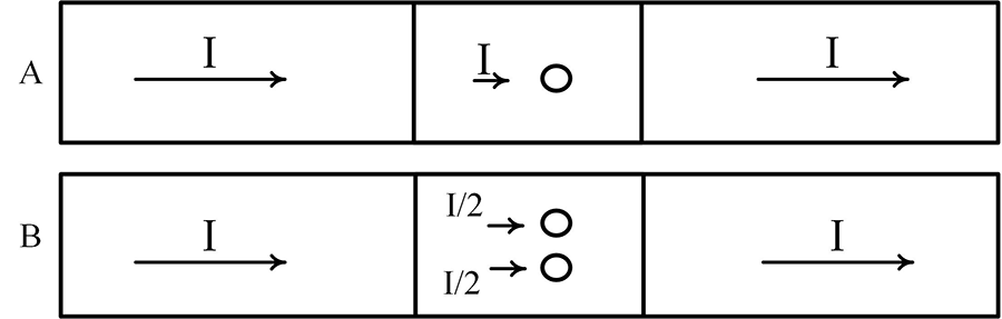
Figure 1. Trace pairs connected with one (A) or two (B) vias.
The power dissipated in any resistance is I2R. (Recall that temperature is related to power dissipation.) This is the power dissipated in case labeled A. If there are two vias, the power dissipated in each via is (I/2)2R = I2R/4, and the total power dissipated in the via pad area is I2R/4+ I2R/4 = I2R/2, or one-half, (1/n), the power in the single via case. In the general case, the power dissipated in each via is (I/n)2R and the total power dissipated in the pad area is n*(I/n)2R = n*I2R/n2 = I 2R/n.
So if the ratio of the conducting cross-sectional areas is n, how any vias, y, does it take to have the same power dissipation in the via pad area as when n=1?
I2R = n*(I/y)2R = n*I2R/y2, or
1 = n/y2, or
y2 = n, or
y = n1/2 = square root of n
The answer is y = n1/2 vias. This means that if the ratio of the conducting cross-sectional areas is n, then n current carrying vias provides the power dissipating ability of n2 vias. In other words, if the ratio of the conducting cross-sectional areas is n, we only need n1/2 (the square root of n) vias to provide the same total power dissipation capability as a single current carrying via when n=1.
Bottom line: If the conducting cross-sectional area of the trace (width * thickness) is n times greater than the conducting cross-sectional area of the via, then only the square root of n vias is required, not the n number of vias common wisdom has previously told us.
Notes
- IPC-2152, “Standard for Determining Current Carrying Capacity in Printed Board Design,” August 2009, ipc.org.
- Brooks and Adam, PCB Design Guide to Via and Trace Currents and Temperatures, Artech House, 2021 (available on Amazon.com). Chapters 8 and 9 cover vias.
- Douglas Brooks and Johannes Adam, “How Many High Current Vias Do We Need? (Fewer Than You Think),” PCD&F, December 2023.
Douglas Brooks, Ph.D. has bachelor’s and master’s degrees in electrical engineering from Stanford and a Ph.D. from the University of Washington. He owned an engineering service firm and has published multiple books, including Physics of Electronics for PCB Designers and PCB Design Guide to Via and Trace Currents and Temperatures; This email address is being protected from spambots. You need JavaScript enabled to view it..


