 White mask is possible, but careful of overexposure.
I am designing a flex circuit that will have LEDs in one area. I would like that area to be white in color instead of amber. What is the best way to do that?
Answer: A flex circuit can have a white outer surface, and this can be achieved in several ways. I will cover the different methods with the pros and cons for each.
Screen printing. For a "quick and dirty" solution, simply have that area of the circuit screen-printed with white ink (over the top of the standard amber polyimide covers). The downside to this method is that if you also want screened legend, a separate process using a contrasting ink color is necessary. Any LEDs must have clearance to ensure no ink ends up on the solder pads. This method will produce a white surface, but there may be rough edges and color tone variations. I would not recommend attempting any tight bend radius forming in areas with screen-printed ink. Some inks can crack if bent sharply, and if a crack forms in the ink it can, and probably will, propagate through the underlying polyimide film over time. And even if the cracks do not propagate through the polyimide film, the ink around the cracks will flake off and end up as FOD (foreign object debris) in the system.
Flexible solder mask. Depending on the application, white flexible solder mask may be a good option. Flexible solder mask comes in a wide range of colors, white being one (Figure 1). The process to apply white solder mask is exactly as any other color or type of solder mask. There is no learning curve unless very tiny openings in the material are needed. If you do have tiny features, the fabricator may have to perform some testing to determine printing parameters. White solder mask is more reflective than the standard green solder mask. This requires a balancing act to stay between fully exposing the solder mask, but not overexposing so that those tiny openings get even smaller or disappear completely. Several colors of solder mask can require fine-tuning in the printing process to account for how the color pigments impact the UV light interacting with the unexposed mask.
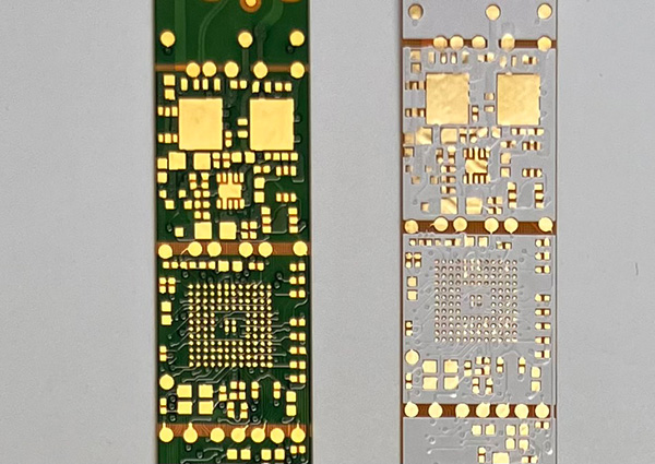
Figure 1. Flexible solder mask is available in a several colors including black, white, amber and green.
It is important to keep in mind that flexible solder mask is more flexible than what is used on rigid PCBs, but not nearly as flexible as a polyimide cover (which is a great segue into the next topic; more on that in a moment). Do not rely on minimum bend radius recommendations from IPC-2223, because those guidelines assume polyimide covers. If you try bending a circuit with flexible solder mask to a 10:1 bend ratio as IPC-2223 allows, the solder mask will almost always crack. I personally would like to see 100+:1 as a minimum bend ratio when using flexible mask. An option to avoid the bending issue is to use flexible solder mask only in the LED area since that area will most likely have some type of stiffener to keep it from flexing. Standard amber polyimide covers can then be used in the flexing areas. The solder mask/polyimide cover combination method will have a little bit of a cost adder but does give the best of both worlds.
White polyimide film. White (or black) polyimide cover film is available from multiple material suppliers. The downside is that this material is not used as extensively as amber polyimide, so it is a lot more expensive and may have a significant minimum order quantity (the MOQ can be more than 100 sq. m.) and longer lead times to procure it. Since the acrylic or epoxy thermoset adhesive that is clad to the polyimide cover film has a limited shelf life, manufacturers don't typically make a lot of it to put on shelves on the chance that it is needed. If volumes are such that you will be able to consume MOQ material inventories prior to the material expiring, white polyimide is a good option.
Any of the methods above do not have to be used on both sides of the circuit unless it is desired. Cost savings can be achieved if colored cover material is only spec'd in the areas that really need it, and is optional over the rest of the circuit. Still confused on the best method for your application? Have a quick chat with your fabricator. They can help you evaluate performance, cost, and lead time to help make the best choice.
Mark Finstad is director of engineering at Flexible Circuit Technologies (flexiblecircuit.com); This email address is being protected from spambots. You need JavaScript enabled to view it.. He and co-"Flexpert" Nick Koop (This email address is being protected from spambots. You need JavaScript enabled to view it.) welcome your suggestions.


