Coupling in differential pairs.
Do corners cause signal integrity problems? Does one line in a differential pair really carry the return current of the other line? Do guard traces really reduce cross talk? Many myths like these propagate quickly throughout the industry, and if repeated enough times, people begin to think they are true.
As these examples illustrate, a myth is a statement that is absolutely true in at least one situation but is incorrectly generalized to all situations. It is important to know when a statement is true and critical to know when it is a distraction, or worse, a bad design guideline. Knowing when guidelines are applicable can mean the difference between a product that works the first time, built on schedule and on budget, or one that’s too expensive or works only after multiple respins that delay commercialization.
The way to separate a myth from realty is by “putting in the numbers,” using either a measurement or a calculation. The ability to use the appropriate analysis tools can be an important empowering skill for all engineers.
One of my favorite myths relates to coupling in differential pairs. I find most engineers believe that the reason to use tightly coupled differential pairs is for noise immunity. When I ask how much noise reduction you would expect from loosely-coupled to tightly-differential pairs, I get estimates of 2x to 10x noise reduction. Is this true, or is this another myth?
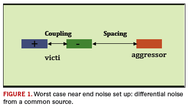
Consider a worst-case example of a differential stripline as the victim line and a single-ended adjacent aggressor line, as illustrated in FIGURE 1. Since there is no far end noise in stripline, the worst case is that the aggressor’s transmitter is adjacent to the victim's receivers.

Any near end noise from the aggressor, that is common to both lines that make up the victim’s differential pair, will not create differential noise. The tighter their coupling, the more common the noise on each line of the pair, and the lower the differential noise expected – but by how much?
The only way to know how much noise reduction there might be from tighter coupling is to use a 2D field solver and “put in the numbers.”
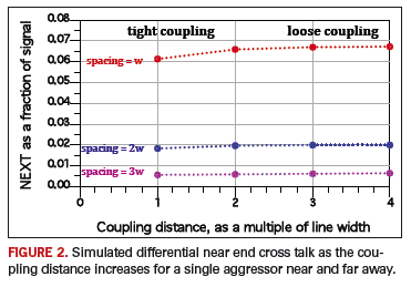
In this example, an active single-ended signal is driven on the aggressor line, and the saturated differential near end cross talk is calculated on the quiet pair. We will keep the spacing between the aggressor and one line of the differential pair fixed and change the coupling between the two lines in the victim pair. The differential pair is 5 mil wide with a 100-ohm differential impedance. FIGURE 2 shows the simulated saturated differential near end noise on the victim line, as a percentage of the signal swing.

Look at the case of the aggressor close to the differential pair, with a spacing equal to a line width. As we decrease the coupling distance between the two lines in the differential pair, going from a loose coupling with a distance equal to twice the line width to a tight coupling with a spacing equal to the line width, the differential noise is decreased from 6.6% to 6.1%. This is about a 10% decrease.
It is absolutely true that tighter coupling reduces the differential noise in a tightly coupled pair– but not by much. If there really was a 6% differential noise, this would probably be disastrous, and you can’t fix the problem by tighter coupling- you need to move the victim pair farther away or find another solution.
There are some important cases where tighter coupling in a differential pair can give higher noise immunity, but you shouldn’t think that in long traces on a board, tighter coupling provides a noise benefit. Tighter coupling might be the right choice, especially if interconnect density is important, but be aware that you may take a hit on losses by using tighter coupling, and you may not gain much noise immunity benefit. PCD&F
Dr. Eric Bogatin covers this and many other SI topics in his classes and on his web site, www.beTheSignal.com. He can be reached at This email address is being protected from spambots. You need JavaScript enabled to view it..


