Two unique equations can be used when fusing a trace – each offering its own strengths and weaknesses.
Up until about 10 years ago, when PCB designers searched for information about the current needed to melt a trace on their boards, only two names popped up in the literature, W. H. (Sir William Henry) Preece and I. M. Onderdonk. Each is credited with developing a unique equation, bearing their respective name, and those equations became the basis for many PCB calculations.
Preece's background is considerably well known. In the 1880s, he was a consulting engineer for the British General Post Office and became engineer-in-chief in 1892. At that time, the Post Office was responsible for the telegraph (and later wireless telegraph) system in England. He published three papers in the Proceedings of the Royal Society of London in the 1880s that formed the basis for his famous equation1:
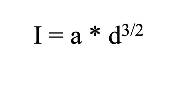
EQ. 1
where d is the diameter of the wire in inches
a is a constant (10244 for copper), and
I is the fusing current in amps.
Interestingly, in the 1890s, Preece became an ardent supporter, both politically and financially, of Guglielmo Marconi and his work on trans-oceanic wireless telegraph.2
On the other hand, almost nothing is known about Onderdonk. I have found no earlier reference than a small article in a 1928 issue of the General Electric Review by E. R. Stauffacher.3 Onderdonk's equation is referenced a few places in the literature, and it is always quoted as a "given" (much like we take Ohm's law as a given.) I have found no original work by Onderdonk.
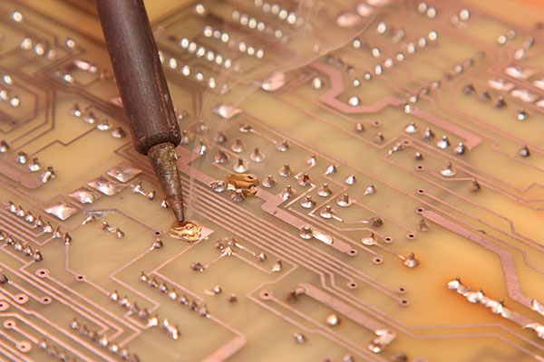
Figure 1. Reaching the point of fusing on the printed circuit board.
Objectives
Preece's objective in developing his equation is clear. He was concerned about how the electrical energy from lightning strikes may travel along the telegraph wires and injure an operator. He was looking for the best conductor material that would a) carry sufficient current under ordinary conditions for the telegraph system to operate yet b) fuse (melt) if a lightning strike caused a current surge. He tested a large number of potential candidates and developed the constant, a, (Eq. 1) for each.
Since we have no original work by Onderdonk, and since Stauffacher's article is the earliest we can find, we infer from Stauffacher that Onderdonk was motivated by a similar problem. The supporting towers for long-distance electrical transmission lines were themselves supported by steel cables anchored into the ground. These cables got covered with dust through time. During periods of rain, the damp wires could conduct large electrical spikes, shorting the transmission line to ground. The question was how large did the transmission line wires need to be to "not melt" long enough for the safety equipment to safely shut down the transmission line?
Interestingly, at this time, Stauffacher worked for Southern California Edison, and the power company was building a long transmission between Southern California and Henderson, Nevada, to support the construction of Hoover Dam. It is possible that Onderdonk created his (her) equation to support that work.
Procedures and Limitations
Fusing (melting) a conductor involves two stages, each taking a certain amount of time and energy. The first is to bring the temperature of the conductor to the fusing (melting) temperature. The second is the time and energy required for the sample to actually melt while at the fusing temperature. This second stage is called the Heat of Fusion.
Preece appears to have been a lab rat. His papers disclose that his procedure was to pass a current through a test sample. He increased the current until the sample glowed a bright red. Just before the sample melted, he recorded the current and called it the "fusing current." Clearly, this was the current needed to bring the sample to the fusing temperature (in his judgment), but not high enough to actually melt the sample. The time to reach the fusing temperature was never a consideration.
Onderdonk, on the other hand, developed his equation rigorously through mathematical derivation. No original derivation by Onderdonk exists that I have found. But Dr. Johannes Adam has independently derived Onderdonk's equation and it has been published in two places.4 This derivation explicitly excludes the heat of fusion, and it explicitly assumes Joule heating through I2R dissipation but no cooling whatsoever.
Equations
Preece's equation is straightforward (Eq. 1). He developed constants for many different materials, but the one of interest to us is the constant for copper. That results in Eq. 2:
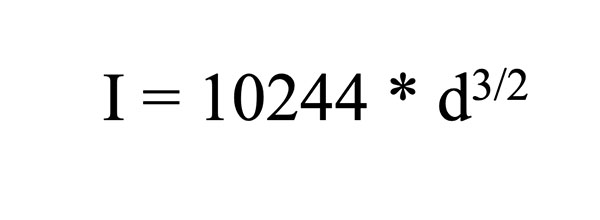
EQ. 2
where, again, d is the diameter of the wire in inches and I is the current in amps. A little algebra transforms this equation into:
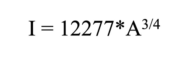
EQ. 3
Where A is the conductor cross-sectional area in sq. in.
For example, let's assume a 1.0oz, 100-mil wide copper trace and see what Preece's equation gives us for the fusing current.
I = 12277*A3/4 = 12277 (.0013*.10)3/4 ≈ 15 Amps
Onderdonk's equation is much more complicated.
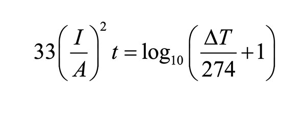
EQ. 4
for T = 40°C, but occasionally in the more general form:
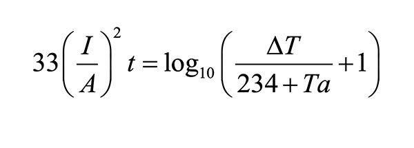
EQ. 5
Where:
I = the current in amps
A = the cross-sectional area in circular mils5
t = the time in seconds the current is applied
ΔT = the rise in temperature from the ambient or initial state
Ta = the reference temperature in °C
We are interested in knowing the fusing current for copper and the time it takes to reach the fusing current at any given current level. Thus, we can do some significant simplifying. Let the ambient temperature be 20°C and the melting point of copper be 1083°C. Then convert A from circular mils to square mils. When we do that, we derive Eq. 66:
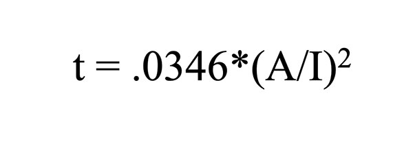
EQ. 6
As an example, assume an application of a 15A current to a 1.0oz. thick, 100-mil wide copper trace. Onderdonk's equation would predict a fusing time for that trace to be:
t = .0346*((1.3 * 100)/15)2 = 2.6 seconds
Relationship between the Equations
Preece's equation gives a relationship between fusing current and conductor area. Onderdonk's equation gives a relationship between fusing current and conductor area, and adds information in the form of fusing time. It is instructive to see that these two (completely independent) equations result in reasonably consistent results. In the examples above, Preece's equation calculated a 15A fusing current for our trace. Onderdonk's equation calculates that that current will fuse the trace in 2.6 sec. Given the nature of the assumptions made in the Onderdonk derivation and the testing apparatus Preece had available to him in the 1880s, these are very reasonable results.
Relevance of the Results
A significant weakness in Onderdonk's derivation is the implicit assumption that no cooling is taking place. Almost everywhere we see this equation published, there is an admonishment that the time estimate is only accurate up to about 10 sec. That is because it applies to a wire suspended in the air. After that time, the "zero cooling effect" assumption breaks down. We have simulated a bare wire in the air with zero cooling and the results fit Onderdonk's equation perfectly.7
Preece's notes don't provide much of a clue about how he applied the current to his samples or how long he spent with each sample. Nevertheless, his results are reasonably compatible with Onderdonk's.
Dr. Adam and I have run many fusing simulations and experiments on PCBs and have found that in this environment (printed circuit board substrate) the cooling effect kicks in very quickly, less than 1.5 sec. Nevertheless, we feel we can estimate fusing times on PCB out to four or five seconds within a reasonable tolerance.
It is interesting to note that if we calculate a trace temperature for a 1.0oz., 100-mil wide copper trace with 15A current using equations derived from IPC-21528 results, we get about 180°C, not the melting temperature of copper. The difference is that the calculations using the IPC-based equations do assume cooling is taking place.
NOTES
- These references are very hard to find. I have collected them for download at www.ultracad.com/articles/reprints/preece.zip.
- A very interesting book covers this time in Marconi's life and his support from Preece, as well as a parallel murder story and how these two stories intersected in 1910. See Eric Larson, "Thunderstruck," Crown Publishers, 2007.
- E. R. Stauffacher, "Short-time Current Carrying Capacity of Copper Wire," General Electric Review, vol. 31, no. 6, June 1928 (www.ultracad.com/articles/reprints/stauffacher.pdf).
- See Douglas Brooks and Johannes Adam, PCB Design Guide to Via and Trace Currents and Temperatures, Artech House, 2021, Appendix G, and also Johannes Adam white paper No. 10, www.adam-research.de/pdfs/TRM_WhitePaper10_AdiabaticWire.pdf.
- A circular mil is the area of a circle with a diameter of one mil. The formula is A = d2. The conversion from circular mils to square mils is π/4.
- For details and derivation steps, see references in Note 4.
- See Brooks and Adam, Note 4, Chapter 12 for more in-depth information.
- IPC-2152, "Standard for Determining Current Carrying Capacity in Printed Board Design," August 2009. Calculations were made with UltraCAD's UCADPCB4.3 Calculator, available for free download from ultracad.com.
DOUGLAS BROOKS, PH.D., has bachelor's and master's degrees in electrical engineering from Stanford and a Ph.D. from the University of Washington. He owned an engineering service firm and has published multiple books, including Physics of Electronics for PCB Designers and PCB Design Guide to Via and Trace Currents and Temperatures; This email address is being protected from spambots. You need JavaScript enabled to view it..


