Thermal interface materials provide much-needed heat relief for electronic assemblies.
Overheating is the number one cause of electronic component failure and requires aggressive thermal management strategies. That’s why thermal interface materials (TIMs) have become ubiquitous in today’s electronic assemblies, working to dissipate heat from heat-sensitive components, improve device reliability, and prevent premature failure.
The two main categories of thermal interface materials are TIM1 and TIM2. Used together, they create a comprehensive thermal management solution at both the chip and semiconductor package level.
TIM1 materials remove heat at the chip level, creating a thermal conduction pathway from the heat-generating chip to its metallic lid. As the first line of defense against overheating, TIM1 materials are vital for long-term reliability. TIM1 materials are formulated to meet rigorous requirements. They must withstand temperatures up to 150°C (in reliability cycling), effectively wet adjoining surfaces, and mitigate heat induced mechanical stresses caused by CTE (coefficient of thermal expansion) mismatches. CTE is a material property that describes the extent to which a material expands and contracts due to changes in temperature.
TIM2 materials remove heat at the package level, creating a thermal conduction pathway from the exterior of the semiconductor package to a heatsink, heat pipe, or other heat spreader. TIM2 materials are the second line of defense against overheating and must withstand temperatures up to 120°C for reliability aging tests.
In use, TIM1 and TIM2 materials will see a range of operating temperatures, dictated by the type of chip with which they are connected. In automotive Mosfet or IGBT chips, operation temperatures can run well over 120°C at the die interface. Operating temperatures are cooler for data center chip packages, and even cooler for portable electronic devices.
Thermal cycling and surface adhesion are major challenges that affect long-term reliability and performance of TIM materials. Raw materials and fillers must be carefully selected and formulated to avoid embrittlement and delamination when exposed to thermal cycling. And they must be able to retain their conformability in extreme environments for the lifespan of the device, taking on the contours of rough adjoining surfaces to fill air gaps and voids.
All electronic components generate excess heat. As electronic devices become smaller, faster and more functional, they generate even more heat in smaller more confined spaces, which can lead to serious reliability issues if maximum operating temperatures are exceeded. This phenomenon is referred to as increased heat flux (measured in Watts/cm2).
Heat is a major reliability issue in electronics, and thermally conductive materials are an essential part of solving the problem of heat-related failures, which is why the TIM market is booming. Grand View Research estimates the global TIM market was $1.84 billion in 2021, and predicts it to expand at a compound annual growth rate (CAGR) of 11.4%, to reach $4.86 billion by 2030.
TIM1 materials. TIM1 type materials are used as the first line of defense to prevent overheating and improve reliability of heat-sensitive components such as ICs. TIM1 materials are typically placed inside the semiconductor package, between the heat-generating chip/die and a heat-spreading metallic lid, making contact with both for more direct heat dissipation. A typical TIM1 assembly configuration is shown in FIGURE 1.
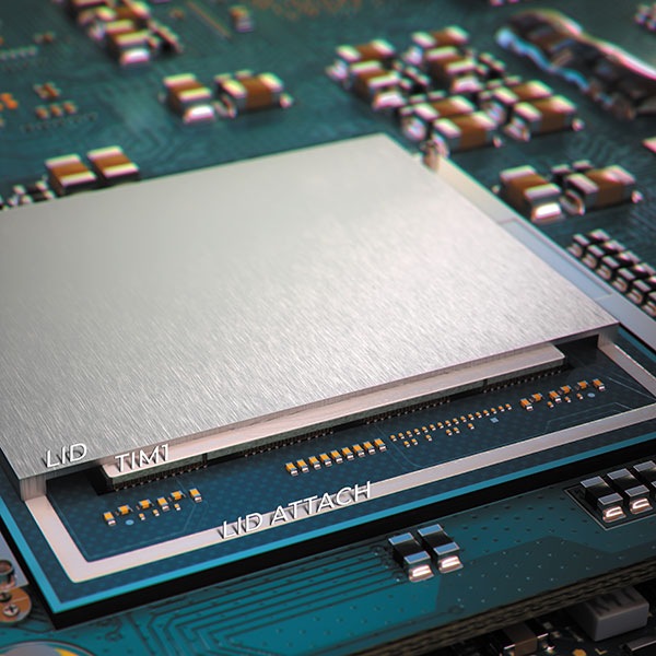
Figure 1. A typical TIM1 assembly configuration.
Increasingly, silicone is used as the base material of choice for TIM1 type materials, and formulations include carefully selected conductive fillers with conductivity and surface wetting. Wetting refers to the ease with which a material bonds with a given substrate. A variety of forces (ionic, static, polar, van der Waals, etc.) act to create chemical linkages and improve molecular attraction to ensure optimal wetting and reduced thermal resistance.
TIM2 materials. For high-heat-generating components – such as TOs, FPGAs, Mosfets and IGBTs – heat sinks, heat pipes, fans and heat spreaders are added on the outside of the semiconductor package. TIM2 materials are utilized in this configuration as the second line of defense to further dissipate heat, prevent overheating, and improve reliability. As shown in FIGURE 2, TIM2 materials are typically placed between the outside of the semiconductor package and a heatsink. When coupled with TIM1 products, TIM2 materials provide extra heat dissipation capability.
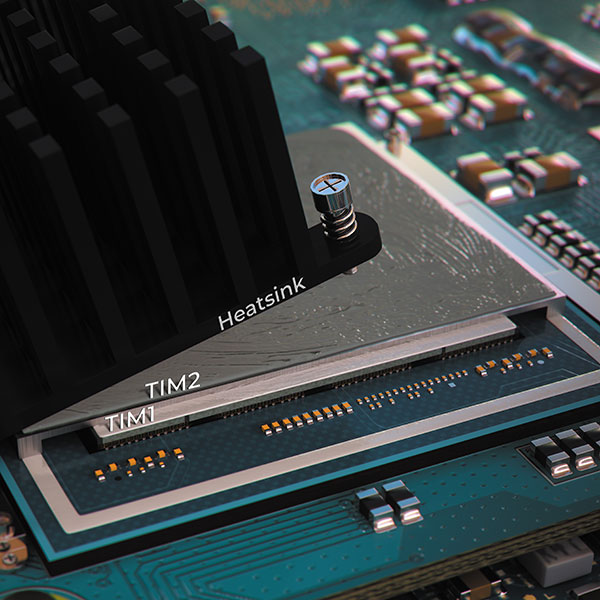
Figure 2. TIM2 materials are typically placed between the outside of the semiconductor package and a heatsink.
Performance Requirements
From a technology perspective, TIM1 reliability and performance requirements are much more demanding than that of TIM2, requiring higher performance fillers and formulations.
TIM1 materials must withstand extreme temperature cycling from -40°C to 150°C, whereas the functional upper limit for temperature cycling TIM2 materials is typically closer to 120°C. While this 30°C difference in the upper temperature limit may not seem like much, it significantly eases the formulation requirements, permitting more variability in base and filler material selections. Certain epoxies or other thermoplastic materials that might otherwise be contenders for TIM1 applications cannot withstand temperatures of 150°C without hardening and delaminating, resulting in thermal failure.
For this reason, most TIM1 materials are silicone-based chemistries to meet the 150°C upper limit, and must also use surface treatments to functionalize the thermally conductive filler particles to endure extreme temperatures over time without becoming embrittled, changing their gel-like characteristics, and inducing mechanical stresses due to high CTE mismatch.
Temperature cycling and reliability. Understanding the relationship between CTE mismatch and end-use environment is important for designing reliable TIM assemblies. Extreme temperature variations can induce significant mechanical stresses due to CTE mismatch between adjoining surfaces, which can lead to delamination of the TIM material.
Heat transfer performance of both TIM1 and TIM2 materials is strongly influenced by the roughness of the surfaces on which they are applied. Surface roughness imperfections, like those illustrated in FIGURE 3, impede heat transfer by introducing microscopic air pockets which act as insulators. Small peaks and valleys on rough surfaces entrap air and increase thermal resistance. To transfer heat efficiently, TIM materials must be sufficiently soft and compliant to fill air gaps and voids. For this reason, most TIM1 materials are designed as dispensable gels that flow and wet adjoining surfaces without introducing compressive stresses, while TIM2 materials are designed to be malleable and deform under compressive stress to fill voids.
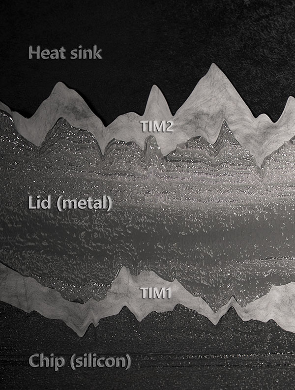
Figure 3. Surface roughness imperfections impede heat transfer by introducing microscopic air pockets.
Mechanics of thermal performance. A common data point on a material’s technical data sheet (TDS) is thermal conductivity, k, which indicates the material’s inherent ability to conduct heat. Thermal conductivity is measured in watts per meter Kelvin (W/mK).
Note that a material’s thermal conductivity value is only one part of a larger equation that predicts the ability of an assembly to conduct heat in real-world applications. The thickness of the thermally conductive material and surface irregularities on the adjoining surfaces also affect the ability of the assembly to conduct heat.
Total thermal impedance, Rth, is a better predictor of thermal performance than the thermal conductivity of the TIM material alone. Thermal impedance, the sum of all thermal resistances through the assembly, is measured in Kelvin centimeter squared per watt (Kcm²/W).
A typical TIM assembly and the calculation of its thermal impedance is shown in FIGURE 4.
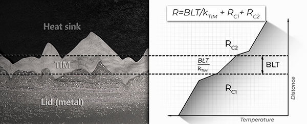
Figure 4. A typical TIM assembly and the calculation of its thermal impedance is shown.
Where RTIM is the bulk thermal resistance of the TIM material, RC1 and RC2 are thermal contact resistances between the TIM and adjoining surfaces.
An assembly that is better at conducting heat (higher k value) will have a lower RTIM value and typically have a lower thermal impedance (lower Rth value) as well, but there are exceptions to this.
If a material has low RTIM, but also has high contact resistance (it does not wet the adjoining surfaces effectively) it may actually have a higher Rth than a material with lower thermal conductivity but very low contact resistance.
Thermal conductivity and bond line thickness. Optimizing bond line thickness (BLT) is one method of achieving lower thermal impedance and improving thermal performance of a TIM assembly. Selecting thinner TIM materials or applying compressive forces to TIM materials are common techniques used to minimize thickness and lower thermal impedance.
In TIM1 applications, however, where mechanical stresses are detrimental to the integrity of the die, adding too much pressure is avoided.
In TIM2 applications where substrates are more durable, conformable gap pads and gap fillers are used under pressure – which is typically applied through a mechanical clamping system. This mechanical pressure helps remove air gaps and voids, and compresses conductive filler particles closer together for improved thermal performance. The goal is to reach compression values that achieve the most advantageous thermal performance (typically 20 to 40psi). Chemical formulations and fillers will affect the pressure necessary to achieve the minimum BLT. As shown in FIGURE 5, when optimized, pressure decreases overall thickness and creates intimate contact between the conductive filler particles, aligning them for the best possible thermal performance.
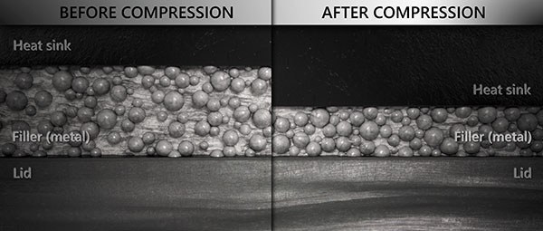
Figure 5. Pressure decreases overall thickness and creates intimate contact between the conductive filler particles, aligning them for optimal thermal performance.
The ongoing movement toward the implementation of 5G telecommunications is increasing demand for advanced TIM formulations. 5G antennas and devices generate more heat than their LTE predecessors due to 5G’s mmWave frequencies. 5G Technology World reports that when designing 5G into a router or other fixed-access device, thermal issues are encountered to a greater “degree” than in products that use LTE for wireless communications, even though the energy-per-bit might be less than LTE. Some mobile phones on the market today are already capable of receiving and interpreting 5G signals, but can do so only for short bursts before the hardware heats up, triggering the software to throttle back performance to protect the electronics and users from heat.
Automotive trends, such as advanced driver assistance systems (ADAS) and electric vehicles (EVs), are also driving the need for new TIM materials. High-speed ADAS electronics that enable improved driver and pedestrian safety, and high-power electronics for EV battery charging and discharging, create considerable amounts of heat. These, along with the potential for harsh temperature extremes in vehicle operating environments, create numerous real thermal challenges for automotive electronics.
Conclusion
A comprehensive thermal management approach not only includes using the right TIM materials in combination with heat sinks, heat pipes, fans and heat spreaders, but also includes a good thermal management strategy that starts during the design phase. Electronic systems can be designed to include thermal management at all levels (chip, package, PCB, and enclosure). Thermal simulations can be run before actual systems are manufactured to identify issues and optimize solutions. For example, PCBs can be designed with thermal vias and copper layers that help spread and dissipate heat at the board level. Solving heat-related reliability issues is complex, involving many different variables that may require unique solutions for each specific application. •
Claire K. Wemp, Ph.D., is thermal applications engineer at DuPont (dupont.com); This email address is being protected from spambots. You need JavaScript enabled to view it..


