New tool features keep the thermal design concurrent with the PCB design.
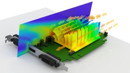
Thermal design for reliability in today’s avionics products is more challenging than ever. Always increasing onboard processing and communication capabilities, along with demanding size and weight constraints, coupled with harsh operating environments, all impact the design team’s ability to effectively manage electronics cooling. As product development teams struggle with the requirement for shorter development time to flight, many are looking to the latest generation of computational fluid dynamic (CFD) analysis tools to provide new approaches to electronics cooling design. Specifically, they are looking for solutions that can bridge the gap between the ECAD and MCAD disciplines to predict airflow and heat transfer in and around the electronic equipment within avionics products. Today’s innovative software solutions can address design and time pressures by bridging the divide between the ECAD development and the MCAD engineering processes. Properly applied CFD analysis can save design time and reduce the need for physical prototyping by helping avionics product development teams create and deliver right-by-design products (FIGURE 1).

FIGURE 1. Electronic cooling CFD analysis.
Traditional challenges. Developing useful thermal and airflow predictive models for electronics in complex avionic systems has historically been challenging. Fundamentally, it is often difficult to effectively include electronic components (PCBs, ICs, fans, etc.) in the modeling. Many modeling tools are in fact very sophisticated with respect to fluid analysis but are basic when it comes to building a detailed electronics cooling model. There are also issues when attempting to build an accurate board-level thermal analysis model. Traditionally it has been difficult to take data from an ECAD PCB design tool into an MCAD CFD analysis tool unless the CFD tool is specifically designed for electronics cooling applications. Furthermore, the engineers responsible for thermal design often don’t have the unique skills required to operate traditional CFD software. While the thermal engineer may have in-depth knowledge of thermal design, they are often less knowledgeable regarding effective utilization of a CFD analysis tool, for example, the meshing approach to use. Finally, there is also the time required to develop a CFD model for thermal design (which may require studying multiple models) that often may be prohibitive to provide value during the design phase.
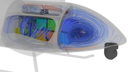
As mentioned, some current software tightly couples the ECAD and MCAD design flows and, as such, reduces design process times by a factor of at least two compared to traditional general-purpose simulation solutions. They are focused solely on electronics cooling (PCBs, ICs, fans, etc.) (FIGURE 2).

FIGURE 2. Airflow distribution.
This is especially important when working with avionics thermal design. These current generation thermal analysis tools are able to add sophisticated board-level models to the CAD geometries that exist in the product. To overcome traditional challenges with the steep learning curve sometimes associated with older modeling tools, these tools are targeted at the design engineer, as well as the thermal specialist. They utilize a CAD-centric graphical user interface (GUI) for the thermal analysis that is similar to the GUI utilized when working with any other type of analysis, for example, signal integrity or power integrity. Specifically, current generation thermal analysis tools automatically filter thermally irrelevant parts, import thermal power lists, have meshing and solver technology for efficient handling of complex geometries, automatically associate appropriate thermal models, and have edit and update functionality to keep the thermal design concurrent with the PCB design.
Such features enable designers and thermal specialists to quickly and efficiently arrive at an optimum solution during product development. The goal is to use CFD analysis throughout the design process from conceptual design to manufacturing, thereby improving product quality, reliability, and time-to-market.
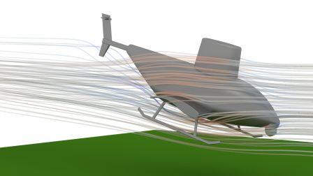
Use case. To illustrate how current generation innovative software solutions can be applied to avionics thermal design, consider the following use case for an unmanned aerial vehicle (UAV) (FIGURE 3). The purpose of this use case was to demonstrate how a best practice electronics cooling CFD process could be used to evaluate both airflow and heat transfer in the avionics bay and the payload bay of the UAV. Specifically, the analysis would focus on the IC component temperatures on the PCBs within each bay. For reference, the relevant specifications for the UAV are as follows:
- Max speed: 120kn.
- Environment: Sea level, 35°C.
- Avionics bay power: 80W for each avionics box.
- Payload bay power: 100W for each PCB.
- Air movers: Ametek Maxiax 35000 (quantity 4).

FIGURE 3. UAV studied in the use case.
Traditionally a study of both airflow and heat transfer would require multiple tools. Some work would be performed in a general purpose tool, and some work would be performed in an electronics cooling-specific tool, with no way to easily share data between the tools. With current generation CFD tools, all the analysis can be performed in one tool, saving time and ensuring accurate and reliable results.
In this use case the design team started with an external sensitivity analysis to look at the performance of the blowers at various UAV speeds and pitches. This initial analysis was a flow-only analysis; heat transfer was not considered. The goal was to simply determine how the operating point in the blowers changed based on the manner in which the UAV was flying. The team’s conclusion was the static pressure drop across the system at 100 cubic feet per minute (CFM) without equipment was 5% of the blower’s capacity. Since the pressure drop was insignificant, the UAV pitch and speed would not be considered for the remainder of the process.
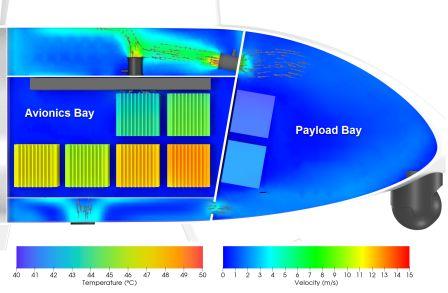
The team then moved on to an internal study of the UAV to analyze temperatures, specifically, how the blowers would influence the heat transfer around the avionics boxes. The goal of this phase of the analysis was to identify the critical areas exhibiting the highest temperatures. The critical areas would then be analyzed in greater detail during the final portion of the process. Focusing the detailed analysis only on the critical areas allows a more rapid turnaround of the overall study (FIGURE 4).

FIGURE 4. Avionics surface temperatures and velocity contours.
The last step of the process was to create detailed PCB models of the aforementioned critical areas within each bay. This portion of the use case also demonstrated how today’s CFD software tightly couples the ECAD and MCAD design flows. The team decided to leverage the MCAD flow when analyzing the critical areas within the avionics bay, and the ECAD flow when analyzing the critical areas within the payload bay. Specifically:
• Avionics bay – convert the MCAD geometry to an appropriate thermal model and run the analysis.
• Payload bay – using the ECAD data, apply the component powers, swap the component definitions with parts from the thermal library, and run the analysis.
The result in each case was detailed temperature maps of the critical areas in each bay that could then be used by the product development team to iteratively improve the product design and reduce dependency on physical prototyping.
Summary. Avionics are the electronic systems used on aircraft, artificial satellites and spacecraft for communications, navigation, the display and management of multiple systems, and the hundreds of systems that are fitted to aircraft to perform individual functions. Such systems need compact and efficient power generation, conversion and thermal management systems. Thermal management is key to designing high-performance, lightweight, reliable systems. The thermal challenge is to remove the total capacity of waste heat with minimal increase in temperature, and at minimal weight and volume. Adding to the challenge is, while the components of the avionics systems continue to get smaller, they are still very power hungry and generate as much or more heat than older-generation components. This smaller packaging of the system makes it harder to have the space for heat sinks and other cooling devices to aid in the dissipation of heat. To meet the demand of increasing avionics functionality, there is a trend to replace the once large systems with multiple smaller systems, each generating the same or more heat as the older system, resulting in a significant increase in the power density of the overall system.
The latest generation of electronics cooling design and simulation applications provides new approaches to the complex requirements for proper electronic cooling and thermal analysis in today’s avionics products. They bridge the gap between the ECAD and MCAD disciplines to predict airflow and heat transfer in and around the electronic equipment, and as such, reduce design process time significantly compared to traditional general-purpose simulation solutions. The current generation of CFD analysis tools have been developed to support different types of design engineers with varying levels of expertise, and to be as usable in early design as in late design verification. All of this enables companies designing complex avionics systems to meet ever increasing reliability requirements in the face of higher performing and power-dissipating ICs in smaller form factors.
John Wilson is electronics product specialist for the Mechanical Analysis division of Mentor, a Siemens Business; This email address is being protected from spambots. You need JavaScript enabled to view it.. Craig Armenti is a PCB marketing engineer for the Board Systems division of Mentor; This email address is being protected from spambots. You need JavaScript enabled to view it..
Register now for PCB West, the largest trade show for the printed circuit and electronics industry in the Silicon Valley! Coming Sept. 11-13 to the Santa Clara Convention Center.


