 How the industry standard revolutionizes PCB collaboration.
Last month’s column talked about a simpler way to exchange stackups with manufacturing partners. This month, continuing the theme of migrating from handoffs to bidirectional design data exchange, we will talk about electronic exchange of technical queries with design/manufacturing partners through IPC-2581’s DfX module. The module may be included within the design data or exist independently, such as a stackup exchange module that can be shared separately.
In the AI age, why does anyone need this? There is a smarter, better way to exchange technical queries – by using IPC-2581 DFM exchange module. Adopting IPC-2581’s DFx module transforms the way PCB designers and manufacturing engineers collaborate, replacing manual, error-prone processes with streamlined, electronic communication. This approach accelerates new product introduction, reduces mistakes and enables both sides to track and learn from every exchange. By making technical queries (TQs) and DfM feedback easy to send, review and act on, IPC-2581 creates a win-win environment for design and manufacturing teams.
Let's examine how technical query data is shared between designers and manufacturers. Then we will review how the same process of exchanging TQs will work with IPC-2581.
Current Design Data Handoff and TQ Exchange
Traditional handoff packages are fundamentally one-way exchanges. Instead of true bidirectional communication, design data are simply handed over, then reverse-engineered by manufacturing partners: Gerber files require full reverse engineering (Figure 1), while ODB++ files are partially reconstructed. After this laborious process, the data undergo DfM analysis, which almost always uncovers issues:
- Mismatches between Gerber and fabrication drawings
- Manufacturing data inconsistencies
- Outright DfM errors.

Figure 1. Traditional handoffs and ePaper-based communication are a lose-lose scenario for the designer and manufacturing partners.
These findings are then relayed back to the designer using ePaper methods – emails, Word documents, PowerPoint slides – tracked manually in spreadsheets. Each ePaper document references specific design structures, coordinates and embedded images to help layout and manufacturing engineers understand the context. This manual correlation is not only tedious; it is entirely unnecessary in today’s AI-driven era. Why can’t tools talk to each other? Why do tools require layout designers to perform nonproductive correlation work that can be completely avoided? PCB designers must be free to perform real layout work.
Manufacturing partners often ask for variance of some rules, chamfering of pads, etc. to improve yields. These variance requests are also sent through ePaper. The approval/disapproval process is through ePaper, and the designer and their manufacturing partners must track these exchanges through emails, spreadsheets, etc. The layout designer manually matches the request’s context, and the pre-CAM process engineer must also ensure the responses correspond appropriately. Any mistake made by either party is costly to both in terms of time lost and wasted materials. Why follow a process that was invented in the 1960s?
IPC-2581 stands out as the only true bidirectional standard, sidestepping the drawbacks of traditional one-way handoffs. IPC-2581 revision C introduced the DfX module, which permits electronic exchange of DfM data and TQs. This module can either accompany the complete set of design data or be distributed on its own, in a manner similar to stackup information.
The latest IPC-2581 release (version 4.0) enhances the DfX module capabilities, thanks to feedback from IPC2581 Consortium and IPC 2-16 committee members. By adopting the DfX Module, designers and manufacturers can finally eliminate ePaper – no more emails, Word docs or PowerPoint slides – saving time and reducing errors (Figure 2). Better, the contextual data exchanged can be analyzed by AI agents to recommend process improvements and minimize unnecessary iterations. Design teams can compare changes across sources, while manufacturers can pinpoint which customers consume the most time, and incent better collaboration. This streamlined process accelerates new product introduction and creates a genuine win-win for everyone involved.
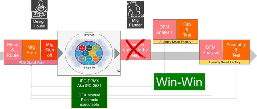
Figure 2. IPC-2581 DfX module queries are sent electronically, understood by the tools on both sides, eliminating manual error-prone ePaper-based communication to accelerate NPI.
What the DfX Module Contains
The module enables seamless, bidirectional communication of technical queries and error reports in an intelligent electronic format, easily interpreted by both design and manufacturing tools. This modern approach replaces the outdated, error-prone ePaper methods of the past.
Within a single DfX module, multiple queries can be included for a given board, ranging from requests for clarification to DfM errors to variance requests on specific design elements. These queries can address a wide spectrum of topics, such as components, assembly, fabrication, stackup, testing, quality, mechanical aspects, materials or footprints. Each query provides detailed information, permitting tools to precisely identify the referenced element. For DfM violations, the module can specify the measurement criteria used in DfX analysis and list any measurements that fall outside the defined standards.

Figure 3. Data flow using IPC-2581 DfX module.
The DfX module also supports communication about conflicts, such as discrepancies between fabrication spec notes attached to elements in the design and reference specifications, or mismatches in drill counts. Each query is linked directly to the design data, enabling tools to cross-reference, zoom in and highlight the relevant elements. External references, such as URLs or files, can be included, and additional items like images, documents, firmware or executables can be embedded in a base64 format.
The DfX Module allows both sides to go back and forth with comments, approvals and rejections.
- Manufacturer (fabricator, assembler) and designer can use their specific viewing formats while sending the information in a neutral format
- Fabricators can eliminate customer-specific TQ formats
- Product engineers can standardize on a common GUI
- Approved DfM can be electronically stored within the IPC-2581 file rather than on an engineer’s disk drive or other database. These data can be stored in the company’s PLM system for streamlined management.
Examples of TQs through DfX Module
Below are some examples of technical queries between design and manufacturing.
Example 1: Query on silkscreen on opening area.
- “Per data file, some silkscreen overlapped onto opening area. We would like to move legend aside if room is available, otherwise we can clip them away from opening.”
- Response
- “Do not move silkscreen. Clip all silkscreen over solderable surfaces and over holes.”
Example 2: Request – add dummy pad.
- Recommended thieving-1
- Unbalanced copper
- Measurement point – layer reference, location x, y
- Marker location and dimension
- Description
- “We can add thieving on internal layers except area of 14a. Thieving pad 50 mil squares spaced on 80 mil centers and keep 130 mil clearance from pattern on adjacent signal layer, no effect for impedance control.”
- Response
Example 3: (from assembler) – Component height analysis.
- Bottom side wave spacing-1
- Location
- BoM reference
- C138, C140, C187, C186, C29, C171
- Description
- “Current heights are 228-531mil, DFM spec is 200mil max in bottom side for wave solder fixture design. Please check and move them to top side.”
- Response
- Rejected
- Comment: “This board will be processed as paste in hole.”
Benefits of Bidirectional Data Exchange with IPC-2581 DfX Module
The module accelerates NPI, creating a win-win for both design teams and manufacturing partners.
For the design team:
- Saves review time for technical questions or DfM errors.
- Returns DfM errors electronically. No more ePaper (PowerPoint, spreadsheets, etc.).
- Direct links from errors to specific design elements make troubleshooting fast and accurate.
- Tracks every feedback and decision, so it is apparent exactly what was done, by whom and why.
- Eliminates manual data entry or interpretation from emails or documents.
For the manufacturer:
- Sends errors and feedback electronically, eliminating need for generating reports in different formats for different customers.
- Easily tracks which errors are fixed, waived or ignored for each design.
- Know who approved, rejected a request and why.
- Metrics are simple to follow over time, whether by customer or by design type.
For both sides:
- Shared metrics over time reveal insights that are hard to see with manual processes.
Conclusion
Embracing the IPC-2581 DFX module revolutionizes collaboration between PCB designers and manufacturing engineers by shifting from manual, error-prone workflows to efficient, electronic communication. This streamlined process speeds up the new product introduction, minimizes errors and allows both teams to monitor and learn from every interaction. By simplifying the exchange, review and resolution of technical queries and DfM feedback, IPC-2581 fosters a mutually beneficial environment for the design and manufacturing teams.
What are you waiting for?
Move to IPC-2581. And leave chaos behind. Reach out to the IPC-2581 Consortium (This email address is being protected from spambots. You need JavaScript enabled to view it.) if you have any questions.
Hemant Shah is an EDA veteran and chair of the IPC-2581 Consortium (ipc2581.com). Shah led the effort to create an industry-wide consortium of design and supply chain companies to get IPC-2581 – the standard for transferring PCB design data to manufacturing – adopted.
He spent 20 years at Cadence as product manager for various PCB design products. Shah also led the industry adoption of the IBIS-AMI algorithmic modeling standard. Prior to joining Cadence, Shah worked at Xynetix and Intergraph. He is passionate about developing and marketing leading-edge software products for PCB design.


