Mitigation techniques and costs of designing around glass-weave skew.
Au: This column is a comprehensive follow-on to the July column introduction on glass-weave skew and the discussion in August of various mitigation strategies. With some overlap, these may be read together or independently.
In July, I introduced glass-weave skew causes and when or why a hardware designer might care. In Part Two, I discussed various mitigation techniques and cost. Here, I’ll do a deeper dive into the impact of glass styles on precipitating or mitigating skew. Part Four will cover dual-ply and low-Dk glass.

Figure 1. Standard glass is shown on the left, with a relatively round yarn cross-section, while mechanically-spread glass – the result of pressure from water jets, typically – is shown on the right.
While glass-weave skew (GWS) is a real problem, it’s hard to characterize because it is statistical in nature. What is the chance one line in a pair will see a different dielectric constant than the other? It depends on the pitch of the lines, the length of the lines, the laminate composition, and the relative chance alignment of the glass bundles under the two lines. Not to say it’s the best way to mitigate glass-weave skew, but glass-style selection provides the least expensive way to mitigate the “fiber-weave effect,” as it’s often called.
The standard. Before we go into the pros, cons and differences between different glass styles as they relate to glass-weave skew, we need to start with concrete definitions and specifications that you can hang your hat on – things that the industry as a whole has already agreed on.
IPC-4412B, Finished Fabric Woven from “E” Glass for Printed Boards, lists 86 different glass styles and their properties. In practice, I’ve only seen 20 of these in use for laminate-vendor construction tables and actual circuit boards. The list is shown in TABLE 1.
Table 1. Yarn Counts, Glass Thickness and Relative Availability for 20 of the 86 Glass Styles Listed in IPC-4412B, Appendix II
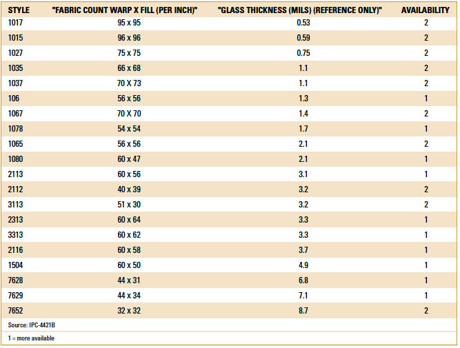
The availability column needs to be considered, to avoid what I call “unicorn constructions.” If a particular construction isn’t readily available at your preferred fabricator, and it also happens to be a “2” for availability in Table 1, there will be lead-time issues.
Not covered in the table or in IPC-4412B are data in the x-y direction, parallel to the glass, that would potentially impact glass-weave skew. We’ll discuss some of these factors below.
Preventing glass-weave skew. Last month, in Part 2 of this series, I outlined a list of skew-control techniques, roughly ranked in ascending order of cost in manufacturing:
- Choose a glass style that minimizes resin windows.
- Choose a glass style with a “square weave” (equal number of yarn strands in the weave and fill directions).
- Route each member of the pair at the same pitch as the glass fibers.
- Align trace direction to the fill/weft.
- Use mechanically spread glass.
- Dual-ply glass
- Half weave pitch jog – halfway down the trace
- Zigzag routing of differential pairs at a 10º angle to the weave
- Build each PCB with the artwork rotated at a 10º angle to the panel and weave.
- Use glass with a lower dielectric constant (closer to the resin Dk).
Numbers 1, 2, 3 and 5 will be discussed in more detail here.
Spread, mechanically spread, or flat? “Spread” glass or “flat” glass are common means of mitigating glass-weave skew. Mechanically spreading or flattening the glass fabric provides several benefits:
- Initially, “flat” glass emerged as a methodology for improving the uniformity of the laser-drilling process.
- Flattened glass also helps mitigate glass-weave skew.
- Improved resin distribution.
Some vendors say spread vs. flat glasses are different, but there’s no consensus on what the differences are. In both cases, glass fabric is pressed in the z direction, either with water jets or rollers.
While it’s been discussed at length, IPC does not have an agreed-upon definition of what we refer to as “spread” glass, one of the means for mitigating glass-weave skew that we’ll address in more detail below. Isola has one definition; Nanya has another; and Nittobo, Asahi or Taiwan Glass have their own as well.
Methods for Characterizing Glass Fabric
Two methods for gauging or quantifying the relative performance of various glass fabric constructions as it relates to glass-weave skew have been proposed to the IPC-4412 task group. Glass manufacturers and committee members are split roughly 50/50 on the two methods.
Air permeability. The ASTM 737-96 test method covers the measurement of the air permeability of textile fabrics, the rate of airflow passing perpendicularly through a known area under a prescribed air pressure differential between the two surfaces of a material. This test is used for woven fabrics and airbag fabrics, for example. Results are generally expressed in SI units as cm3/s/cm2 and in inch-pound units as ft3/min/ft2. Lower air permeability results signify more fabric coverage (high Dk) and smaller air gaps (lower Dk “resin windows”). The best glass styles for mitigating glass-weave skew are those with the lowest air permeability.
TABLE 2 shows air permeability test results for Nan Ya glass, the market-share leader in electrical-grade glass fabric that’s used by many copper-clad laminate manufacturers in Asia, along with glass-coverage area, discussed in more detail below. (Note: All Nan Ya glass is mechanically spread.)
Table 2. Air Permeability and Glass Coverage Test Results for Glasses from Nan Ya Plastics

Optical measurement of % coverage. This method employs an optical microscope, digital camera and digital-image analysis software to assess the glass-coverage area versus the air gap area. Results are usually reported as percentages.
FIGURE 2 shows how optical-measurement images are used to determine glass-coverage percentage (green) vs. resin coverage (yellow). Ideally, for mitigating glass-weave skew, we would want the glass coverage percentage (green) to be as high as possible. Some will say the smaller resin windows are a problem for proper resin encapsulation, and that’s a legitimate concern, but modern laminates and high-layer-count circuit-board fabricators have learned to work around narrower resin-flow paths. Higher glass coverage means there’s a higher probability two halves of a differential pair will “see” the same or similar Dk environment along the signal paths, all other things being equal.

Figure 2. Optical measurement images are used to determine glass coverage percentage (green) vs. resin coverage (yellow).
Horizontal and vertical lines in the image emphasize that glass yarn wanders a bit in practice.
The graph in FIGURE 3 correlates these two measures by glass style, incorporating the results of Table 2. The vertical axis is air permeability, and the horizontal axis represents glass coverage (%). Glass styles that would be better for glass-weave skew mitigation are shown to the bottom right. These constructions have low air permeability values and relatively smaller resin windows.

Figure 3. Air permeability and glass coverage test results for single-ply glasses from Nan Ya Plastics.
A couple of things are important to note here. First, these results are for single-ply glass constructions. While dual-ply glass costs a bit more than single-ply glass for the same dielectric thickness, dual-ply glass – or more generally, multi-ply glass – turns out to be an extremely effective way to mitigate glass-weave skew. Second, it’s important when looking at the graph to compare single-ply glass styles that tend to be used for the same dielectric thicknesses. In this respect, 106 glass should be compared to 1067 glass, rather than 2116 or 3313 glass, for example. Groupings by core thickness are shown in yellow in Figure 3. According to these data, thicker single-ply glasses are consistently better than thinner single-ply glasses.
For similar core thicknesses, you can see 1067 glass is better than 106 for a 2.0-mil core. For a 2.5-mil core, 1078 glass is better than 1080. For 3 mil cores, 1086 would be considerably better than 1080. For 3.5 to 5.0 mil cores, there’s a good bit of consistency between 2116, 2113, 1078, 1086, and 3313 single-ply glass styles. We can’t say for sure these relationships hold for other glass manufacturers, but it’s an interesting starting point for follow-on analysis and comparisons and for making initial tradeoffs while performing stackup design.

Figure 4. Differential-impedance targets were achieved while matching differential pitch to the adjacent glass-fill pitch. (Shown with Z-zero Z-planner.)
Square weaves. Some designers and PCB fabricators prefer “square weaves” over the alternative. A weave is informally classified as being “square” when it has an equal yarn count in the warp and fill directions. (See Table 1.) The concept is tied to the fact that square weaves have the same pitch in both directions as well. For this reason, if the design team is interested in matching the differential pair pitch to the glass pitch, it’s possible to do so without worrying about how the board is oriented (“laid up”) on the manufacturing panel. (See Part 2 for more details on panelization.)
Conclusion. It gets more complicated when laminate manufacturers get glass from different sources, as many do. Who’s tracking where the glass came from, as well as the glass characteristics in the x-y direction? At what frequency should you care? (See Table 1.) This is something I’ll expand on in a later column.
Here, we addressed glass-based mitigation techniques (i.e., 1, 2, and 5 from my list of 10 mitigation strategies), but there’s more to cover, including dual- or multi-ply glass, low-Dk glass, techniques in combination, and expanding on some of the different offerings from various laminate vendors. These will be covered in Part 4 of this series, where we’ll hopefully tie this all together.
I’m interested in hearing comments if this article rang a bell, or download the evaluation software that includes a tutorial for mitigating glass-weave skew from z-zero.com.
Bill Hargin has more than 20 years’ experience in PCB design software and materials. He is director of everything at Z-zero (z-zero.com); This email address is being protected from spambots. You need JavaScript enabled to view it..
He is speaking at PCB West in September.
Register now for PCB West, the leading conference and exhibition for printed circuit board design! Coming Sept. 9-12 to the Santa Clara Convention Center. pcbwest.com


