
Increasing distances between rigid areas helps prevent potential damage.
When designing a rigid-flex that needs to bend 90° in the flex area, what is the minimum flex length (distance between rigid sections) one should allow?
That is a loaded question without knowing the overall thickness and width of the flex layers. For this column, I will assume only a couple of flex layers, and the flex width is 2" or less. Several issues come into play when determining the minimum distance between rigid areas on a rigid-flex. Some will affect the supplier’s cost because of yield reductions, and others may affect the mechanical function.
Manufacturing issues. Fabricating a rigid-flex circuit means juggling a number of technical issues to get everything to work. First, the rigid material must be removable in the flexing areas. (The rigid material is applied in full sheets.) This can be done by pre-scoring the rigid-flex interface lines part way through and removing the adhesive in the flex areas used to bond the rigid material to the stack.
The other method is to pre-route the rigid sheets to completely remove the rigid material and adhesive in the flexing areas only. With the latter method, it is common to add a “pouch,” a single layer of polyimide film used to protect the flex areas from the various plating chemicals during processing. The “pouch” is then typically removed after the final outline routing process.
In either of those fabrication methods, openings in the adhesive used to bond the rigid material to the stack must be lined up with the pre-score or pre-route windows in the rigid materials. A bit of misregistration during this process is typical. If you have a very short distance between rigid sections, this error can be a serious issue. Also, the registration process typically needs to be performed on both sides of the panel, so any potential alignment error could be in opposite directions, therefore doubling the damaging effect. And the smaller the distance between rigid areas, the more impact these misalignments have on final product performance.
Currently, most rigid-flex designs employ “cutback” or “bikini” cover construction to reduce the amount of thermosetting adhesive film in the plated through-holes in the rigid areas. This requires the covers on the flexible layers be removed in all rigid areas. To do this, the cover materials are pre-punched to remove the materials that fall in rigid zones. If the flexing areas are very narrow, the small slivers of polyimide cover material that remain in the cover material sheet after punching are extremely flimsy and dimensionally unstable. Again, this has to happen on both sides of the board, so twice as much chance for error.
Adhesives used for bonding the rigid materials to the stack are usually no-flow prepregs. While the name is “no-flow,” it does flow. The fabricator tries to predict the amount of flow expected along the edges of the rigid material and pulls back the adhesive, so during lamination the adhesive flows to – or slightly short of – the edge of the rigid board. Again, some misalignment is to be expected, and, as a result, the adhesive may flow slightly beyond the rigid edge in certain cases. The excess flow is usually minimal, but in cases with very short flex regions, it could affect board performance when bent. This condition will usually occur on both sides of the board.
Mechanical performance issues. In rigid-flex designs that have very short flex areas, tension and compression forces associated with the bending operation are concentrated into a much smaller area. For this reason, if the distance between rigid sections is short, the thickness of the flexible layers needs to be kept as low as possible. Unbonded (loose leaf) construction is really not a viable option to increase flexibility in any application where the space between rigid sections falls below ~0.75". In addition to the aforementioned misalignment issues, unbonded construction presents the fabricator with additional layers of pre-punched adhesives between the flex layers that also need to be aligned to everything else. Unbonding flexible layers result in the buckling of the innermost layers in response to the compression forces exerted on those layers when the circuit is bent (FIGURE 1). This buckling may result in a dangerously sharp bend radius at the rigid edges, which could cause cracks in the copper traces.

Figure 1. When the circuit is bent, unbonding flex layers result in the innermost layers buckling.
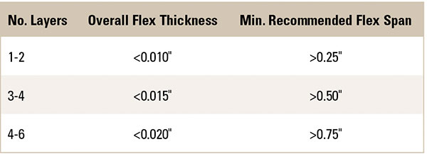
It is difficult to provide a hard, fast number to use as a guideline, since it is significantly impacted by the overall thickness/number of layers of the flex traversing between rigid sections and the overall width of the flex area. TABLE 1 shows my very general recommendations, assuming all flex layers are bonded together, and flex length is 2" or less. Some flex suppliers can do smaller flex zones, and others need more room, but this gives you a place to start.
Table 1. Flex Span Guidelines
You can certainly improve on these numbers, but expect to see a cost bump from the supplier if they are pushed to improve on these guidelines too much. Also, these are minimums! If your design permits a larger distance between rigid sections, take advantage of that. Increasing the distance between rigid areas helps spread out potentially damaging forces when the circuit is bent.
You may also want to pass on adding strain relief if you are really shrinking the flex zones. Considering the average epoxy bead width is 0.030" to 0.060", and you would be adding along both rigid edges, a lot of space will be eaten by just the bead.
Mark Finstad is senior application engineer at Flexible Circuit Technologies (flexiblecircuit.com); This email address is being protected from spambots. You need JavaScript enabled to view it.. He and co-“Flexpert” Nick Koop
(This email address is being protected from spambots. You need JavaScript enabled to view it.) welcome your suggestions. They will speak at PCB East in April.


