 Rigid-flex brings the best – and worst – of both worlds.
Combining all aspects of a flex circuit with a rigid board that makes full use of HDI techniques is one of the breakthroughs of our time. The stacking connectors for board-to-board or the typical flex circuits are bypassed. If you've ever tried to connect a flex circuit to a stacking connector, you know that's a bottleneck in the process – blindly positioning the flex connector over the mating connector can be fiddly to the point of destroying the connectors. Now what?
Rigid-flex projects remind me of digital/analog projects: the best of both worlds and the worst of both. Just for starters, if the team is taking this route, you know they are serious about holding things together with all possible integration. Both technologies are well understood on their own, though the rigid camp is larger and better understood.
Flex circuits on their own. Flexible printed circuits (FPCs) require more than a change of materials from their stiffer cousins. Additional tolerance must be designed into the data. Reason: The different types of material stacks used in the manufacturing process. For the most part, a flex will also have a rigid section where the connector is mounted. The stiffened area could also be extended to host the ESD protection, an LED or microphone; we're flexible.
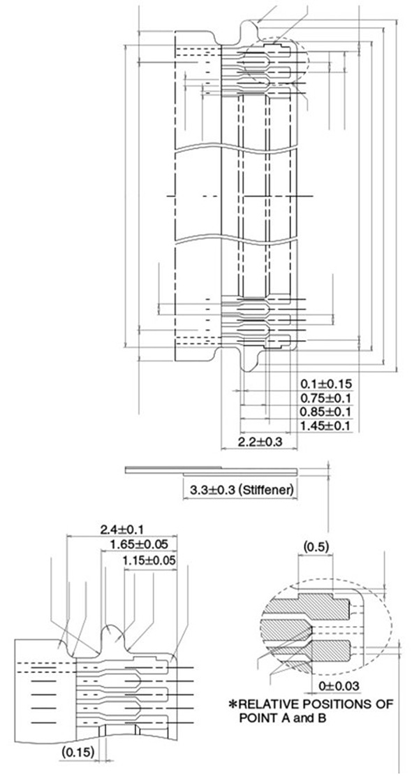
Figure 1. A printed connector with staggered pins. Capturing this footprint manually was no picnic. Thankfully, they are downloadable these days. (Source: Hirose)
A good example of this is a zero-insertion force (ZIF) connector that can be printed on the flex. That approach offers a stiffener at the tail of the FPC that provides a backstop for the pins. It slides into a mating connector, and a lever on that connector locks the flex tail in place. I prefer these to the stacking connector method, whether it's a pure flex or a rigid-flex. Assembly is easier with ZIF connectors.
A rigid-flex use case. Contributing to wearable technology provides interesting outlines. At one point, there were circular islands where we glued on a stiffener in the middle of the flex. Small colonies of components clustered over the stiffener islands while circuitry passed by on all sides. Rigid zones were built into the augmented reality helmet where it passed by the ears, among other locations. Tour an FPC factory or see their boards at a trade show booth; the applications are widespread. I, for one, can't seem to get away from them.
Something like eye tracking required a more sophisticated approach. A 12-layer board isn't a flex no matter what you use for the dielectric material. I've only read about the semi-flexible boards. That sounds cool. With rigid-flex, you get all those extra layers where they are needed.
Then there's the flex core jutting out to get busy with a specific collection of nets. The configuration I've seen most is a three-layer flex inside an eight- or 10-layer board. An odd number of layers starting with a single sided flex for ultimate flexibility is not uncommon.
Figure 2. Note the radius where the flexible core extends from the rigid section. This plus a bead of epoxy act as stress relief for the flex tail. (Source: Cadence)
The advantage of rigid-flex. The polyimide core stackup opens the door for components on both sides of the rigid area. Most of the time, the form factor is going to be "as small as you can make it." This isn't a low-tech solution, so you know the problem you're solving is going to be complex. Enter the ball grid array (BGA) and all its little constituents. Smaller BGAs support the bigger ones, though they may wind up on a different piece of rigid material elsewhere in the rigid-flex board.
Sticking with the AR theme, one of the use cases was an antenna flex extension where the location and orientation of the antenna was part of the overall product outline. The radio chip was on the rigid-flex board so the remote antenna would be part of the flex appendage. Special cases like that might also get their dedicated layer of EMI shielding.
This EMI suppression material must be soldered to the ground mesh that is selectively filled in for the purpose. A small number of slots must be cut in the coverlay to expose those filled areas since the EMI film goes on last. These things need to be accounted for in an extended number of artwork layers.
Being a good neighbor is a universal goal. Coexistence is always front of mind, especially early on. Once a working solution is found, try removing the safeguards to see if it still meets the design criteria. That's what we call lean design, as the parts count reduces over time. In practice, it's just as likely in the early goings that the design will want more filters or some other improvements that add to the parts list.
If you're familiar with the FPC process, then you know the transition from the stiffened area to the flex area is one of the pain points. The same holds true for exiting a rigid zone. The polyimide spans the entire rigid zone plus any flex excursions out to their destinations. Those destinations can have an entirely new board with the same construction as the primary rigid zone. Otherwise, the usual type of stiffener and connector options are in play.
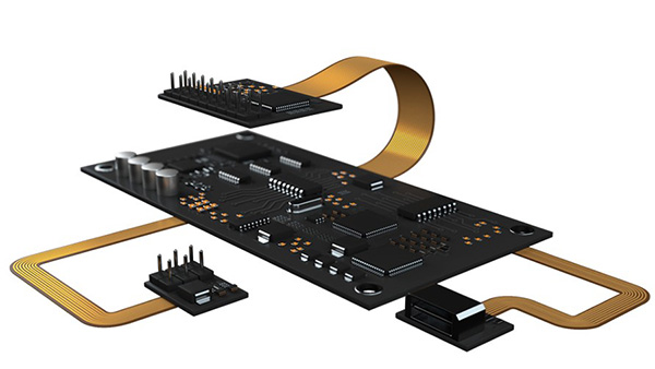
Figure 3. The options are endless with segmenting electronics over rigid-flex designs. (Source: Cadence)
What you don't get to have is a four-layer board in one location and a 10-layer in another. It's all baked as the same layer cake, so the lamination process is the same for all multilayer rigid sections. At the far end of the flex tails we can deploy the usual assortment of flex geometries. We usually picture a connector, but it could be any sort of component mix that can be implemented on a single-sided FPCA.
Routing controlled impedance lines on a rigid-flex PCB. This scenario comes up often. We want to extend some differential pairs from the rigid zone out across a flex zone. We have to assume a three-layer flex with ground mesh on the outer layers and signals inside the Faraday cage. That's the table stakes for controlled impedance. Having the signals in the center of the flex stackup reduces stress on the signals as they occupy the centerline of the flex stack. A two-layer approach stretches and compresses those traces where the flex has a bend region.
We want to maintain the impedance from inside the rigid zone to outside. The way to do that is to continue the mesh on the outer layers of the polyimide wherever those traces may go. Beyond that controlled impedance routing region, it's more likely that we would go with a solid ground plane on those outer flex layers. We're not maintaining flexibility, but we are maintaining the reference planes above and below the transmission lines.
If you want to cut down on connectors with their inherent failure modes and assembly challenges, rigid-flex might be the way forward. They take more time to floorplan and get them to conform to the fabricator's limitations, but the results in assembly can be their saving grace. The increased reliability is just icing on the cake. You can be rigid and flexible at the same moment.
John Burkhert Jr. is a career PCB designer experienced in military, telecom, consumer hardware and, lately, the automotive industry. Originally, he was an RF specialist but is compelled to flip the bit now and then to fill the need for high-speed digital design. He enjoys playing bass and racing bikes when he's not writing about or performing PCB layout. His column is produced by Cadence Design Systems and runs monthly.


