New tools help global design teams meet time-to-market constraints.
Regardless of the industry segment, today’s consumer products nearly universally follow the trend of greater complexity in a smaller package. In this scenario, the electronics must not only meet the electrical guidelines, but also must meet specifications driven by usability and appearance. Design is no longer a single team task. Global design teams are part of the footrace to reach market windows on time. Parallel design activities are key to winning the competition in a world of products with ever-shorter lifecycles. Adding external design partners as well as outsourcing services for production requires new ways of design collaboration. True collaboration removes compartmentalization of responsibilities and enables cross-domain cooperation as the new business model.
However, this new design methodology is not really reflected in current CAD design systems. Currently, CAD systems are segregated between electronic design and mechanical design. ECAD defines the design process for PCBs, and MCAD defines the enclosure design in which this PCB is mounted.
As both design domains have become more sophisticated and specialized, systems have been developed for each, and the gap between the two disciplines has widened instead of narrowed. This has led to increasing design team communication problems and inefficiencies during product development that cannot be addressed with either existing interface standards or paper. The problem only gets worse with today’s trend toward the globalization of companies and the increase in design and manufacturing outsourcing. The most used collaboration method for fast results is still a common meeting where the recognized problem gets pointed out.
Explaining by pointing a forefinger at a display or drawing is the most common method of cross-discipline communication. During this process, those involved are moving from one system to the other, and each designer shows possible solutions using his system, and is influenced to try other options by the cross-domain partner. Working in a CAD environment is preferred since it allows recognition of issues that can arise due to poor decisions in the process. This process is possible if both partners are working in the same building or site, but for a global team, travel cost and time restrictions in many cases prevent this approach.
Moving the Manual Methodology Toward More Automation
Mark-up and red-lining is one way the industry has addressed this problem. But it does not provide direct feedback for the intended change. Synchronization of changes requires strict workflow guidance. But still, inconsistencies are discovered too late in the process in many cases. The result is that each partner works for some time on the assumption the requested change will be executed, and that can cost additional time.
Another option is working with one system that represents both domains. But significant interdisciplinary training is needed to ensure that such a system is fully utilized in both domains and inadvertent changes are prevented. Even by adding cross-domain knowledge, the wall between the domains is not significantly lowered unless the corporate organization is altered to support the cross-function model.
CAD tool designs have further opened the void by becoming more specialized. Today, ECAD and MCAD systems are designed to give the highest performance and handle all aspects of the specialized application. Therefore, unneeded information used for the other domain has been eliminated, and the systems are subjects of totally changed design paradigms. In simple words, MCAD design tools cannot be used to represent and show electrical functions, and ECAD design tools do not allow the design of mechanical elements and assemblies.
However, connectors still must be designed onto PCBs so they do not mechanically interfere with other components or traces. Applied clearance models for interference checks and electrical isolation insurance are not really compatible and can be better solved in the native CAD environments, which are specialized to perform either the mechanical or electrical inspection.
While the current ECAD and MCAD systems have higher performance and richer feature sets, collaboration between both worlds has been treated like the ugly stepchild and is reduced to bills of material (BOM) integration and limited or restricted to file transfer. For data exchange, interfaces like DXF, IGES, EDI or IDF are used, but they don’t allow design updates in a selective or incremental way, nor do they identify the selected objects by name or owner. Specific design elements such as mounting holes in some systems cannot be distinguished from each other. For shared CAD objects, synchronization mechanisms are completely missing. Unintended changes in one system because of an incorrect grouping or an accidental “include†in a movement operation are sometimes only recognized once a prototype has been built. The solution to these limitations is an interface standard.
STEP Combines Interface Standards
The standardization process is widely used in the industry. The non-profit German ProStep iViP association offers a platform allowing the collection of a set of basic requirements and processing guidelines for collaboration from its members, as well as from other invited mechatronic companies. Under the leadership of Mentor Graphics and the ProStep umbrella, a workgroup has been established with members representing users, consulting partners and vendors. In a series of workshops, the idea of a new data model that eliminates well known limitations and rebuilds the traditional way of collaboration in a new service-oriented environment has received strong support and attraction. Many companies contributed with user cases and process scenarios to ensure all aspects of collaboration were covered. The main requirements were related to ownership, network architecture, team organization, IP protection and usability of applications built using this collaboration data model.
The question of which standard to use was one of the first issues. STEP (Standard for the Exchange of Product Model Data) interfaces have been actively implemented to access layout and design systems for board and harness design. STEP complies with AP203 (mechanical design exchange), AP210 (PCB data exchange), AP212 (electric systems), AP214 (mechatronic structural data exchange) and AP233 (configuration management) models that, in combination, can reproduce most of the design objects and give lifecycle support for release and change processes. Furthermore, STEP has been introduced in manufacturing, aerospace and automotive industries with high acceptance.
To avoid “reinventing the wheel,†STEP AP214 has been identified as the guideline for implementation of a new collaboration model at a high-level definition. Instead of exchanging all design data, a common collaboration space for MCAD and ECAD has been defined with some additional extensions from AP 210 (PCB). This collaboration space uses the terminology of the existing mechanical, as well as electronic design tools, and has been transferred in an XML collaboration model. Only a common standardized XML data model allows the flexible development of new collaboration applications in tight integration with the native design tools. The XML model and messaging connects two different domains, but does not hinder development activities nor narrow the feature sets of the native CAD tools. The model supports the process with workflow methods and contains all required information about the collaboration objects. Other electronic design process steps also can be integrated using this communication method.
Every domain is responsible for ownership of the function and integrity of its design and, therefore, for the release steps. Even if changes are proposed, acceptance and implementation must be made by its owner. That means collaboration technology must foster an ownership model that prevents unauthorized changes but allows “what-if†scenarios. Design proposals from both domains should not be limited by the ownership model, as long as test and validation happens in a sandbox and doesn’t have influence on real designs. Definition of boundary conditions, tolerances and solution spaces is helpful to allow independent activities based on given guidelines.
The sandbox has to provide feedback to the users about applicability of changes and is connected to the native CAD model of both domains. Only by acceptance of both domains’ business processes can the ECR/ECO (engineering change request/order) or direct takeover of changes transpire. How changes will occur depends on the established company policies and workflows. Especially for all CAD elements that are shared or required to make decisions about modifications, the collaboration module must be based on a living data model. This model must be aware of the differences and histories, must generate the notifications from one system to the other and must synchronize the changes after acceptance or revision. Such a model enables the protection of IP. This model does not fully open the system’s data set, but filters the requests to provide only those elements really necessary to fix a problem. Furthermore, the application can represent the system in a way that is commensurate with the user’s experience level.
Taking into account network performance, organizational structure, territorial distribution and time zone differences of design teams, a different collaboration paradigm must be created. For those members working in different time zones, asynchronous collaboration respects working hours, but allows engineers in identical time zones to also apply their own time management and prioritization.
In other cases, discussion about changes is better suited to a phone connection. In this case, synchronous collaboration has been seen as the better solution. The participants can follow the discussion of specific scenarios on the screen and exchange their suggestions and findings. For both peer-to-peer engagements and consultation of larger teams, a data model must support agreement about the applicability of changes prior to final implementation.
Training users and the extensive learning curve makes the changeover somewhat expensive. This can be mitigated if existing models are applied or the application is integrated with the existing tools as an additional module under the same usage paradigm. In a sandbox environment, MCAD can contribute to mechanical tests like collision, air flow and stress. ECAD can concentrate on electrical design rules starting from timing requirements and routing ability that must meet given isolation classes. Both domains get these results in their native tools and can inform each other about design limitations or hazards that could negatively affect the other design domain.
Mark-up and red-lining technologies are seen by the user as an instrument to highlight changes or to point out specific areas of interest and, therefore, are part of the envisioned data model’s documentation capabilities.
A Simple Modification Process Example
Let’s take a simple example: moving any design object in a mechatronic design. The term “item†has been used in the collaboration model to identify CAD objects and to give them characteristics. This removes limitations on future unknown design elements. Every item has its own ownership, history, properties and relationships. In our example, the item is a mounting hole and a component. The mechanical engineer would like to move his mounting domes and the position of a component. This requires collaboration with the electronic engineer’s layout system. Using an asynchronous process, he proposes a change in his collaboration model, and the service notifies the ECAD designer about his request.
|

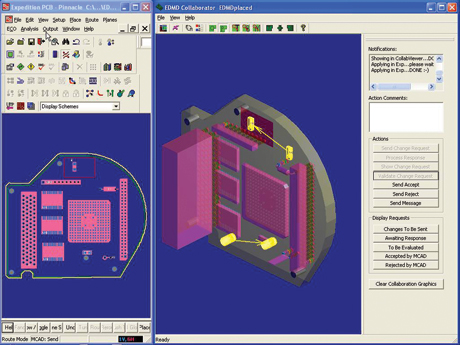
FIGURE 1. A mechanical engineer has proposed moving two items on the PCB design.
|
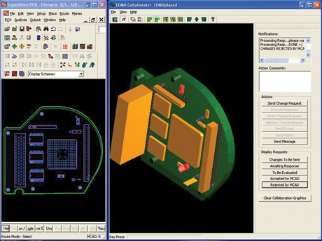
In the ECAD collaborator, this proposed change is shown in highlighted 3D (Figure 1) without any influence on the parallel visible native layout. By pushing the Validate button, the change is accepted and sent to a sandbox environment, which runs the DRC check routines. With a successful checkout, the engineer can accept the change by pushing the Accept button. But if design hazards are recognized and no other solutions are viable, the engineer can push the Reject button. Rejecting a modification reestablishes the previous design in the system and notifies the MCAD designer about the rejection. This does not allow the MCAD designer to progress with the change and undoes the initially proposed modification. Figure 2 shows how the rejected proposal appears on the tool’s screen.
|

FIGURE 2. The red highlights show the proposed change was rejected.
|
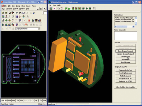
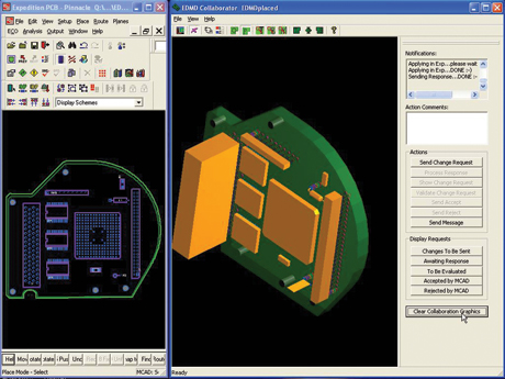
The originating engineer can propose a revised change, as shown in Figure 3. If the engineer using the ECAD system accepts the change, several processes can be implemented, depending on the company’s release policies and PLM (parallel lookup memory) structures. In the simplest case, ECAD notifies MCAD and both continue with the synchronized change. The final accepted change is shown in Figure 4.
Either domain can initiate the collaboration process. In real life, every change request cannot be evaluated immediately, and multiple requests might be queued. Workflow mechanisms track each individual process and can be used to document the process for quality or tracking purposes.
|

FIGURE 3. A new proposal for change; note that the originally rejected change is still visible for reference.
|
This prototype implementation has been used to validate the collaboration data model. In a future product, additional features will be supported. To decouple change requests and open up multiple choice solutions, the collaborator will work with solution spaces and will be able to watch given boundary conditions. Chat functions will allow messaging between partners.
|

FIGURE 4. After the change is accepted, the rejected change is removed and the highlighting removed.
|
IP protection and design setup functions for the easy start of collaboration are also necessary. Links to PLM and integration in library management systems will allow the management of ECAD libraries in combination with 3D part libraries, which might be available in different formats, such as VRML or J-T. This will allow the designer first to do collision reviews in her/his own environment before engaging the mechanical domain. Since the data model ensures only the owner of a design object is allowed to make changes in the native design, even unintended changes in the sandbox produce notifications to the owner. Additionally, filtering and selecting dedicated product elements can help users in collaboration situations where the protection of their own design know-how is key to keeping a competitive advantage. Selecting only those elements that are required to understand and visualize the problem is controlled by the user.
Looking Ahead
Such a collaboration method also allows for the generation of a baseline for a mechatronic-driven design without the use of other exchange standards. It will substitute IDF with a richer feature set and provide access to additional board elements to support better integration in mechanical designs.
With this methodology, one of the last rationalization roadblocks is opened for time-saving and enables design process improvements. The highest goal addressed is the increase of a designer’s creativity while solving difficult design tasks that can only be addressed in a cross-domain environment. PCD&M
Hans-Ulrich Heidbrink is director strategic business development, collaboration projects with the System Design Division of Mentor Graphics Corp. He can be reached at This email address is being protected from spambots. You need JavaScript enabled to view it..


