 From glob top to lamination, solutions for sealing parts in flex.
I need a flexible circuit with a temperature sensor on one end. I need this area to be as thin as possible and sealed against liquid ingress. How do I accomplish this?
Several ways will do what is described. Each has its own benefits and associated costs. I will cover each of them below.
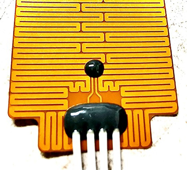
SMT-mounted sensor with conformal coating. The most straightforward solution is to simply mount a standard surface mount NTC or other sensing device to the flex, then seal it with a conformal coat. The conformal coating is typically an epoxy like 3M 2216. This will seal the component and ruggedize the sensor’s solder joints to keep them from damage during assembly or subsequent handling (Figure 1). The downside to this option is the sensor and potting will protrude above the surface of the flex, and depending on the size of the component, this could be significant. Also, the potting is basically a “glob top” where a predetermined dose of epoxy is dispensed over the component and permitted to flow over the top to cover the component and surrounding area. This usually does not produce a perfect circle or oval footprint on the flex, so expect a fair amount of variation. But if there is space above and around the sensor, this is the easiest and least expensive option. Thinner conformal coatings may be used to seal the sensor (e.g., spray-on type), but those will not offer the mechanical protection of epoxy. Potting may also affect the sensor’s sensitivity and responsiveness.

Figure 1. “Glob topping” epoxy is a cost-effective way to ruggedize and seal SMT components and lead wires.
SMT sensor mounted under cover layer. This version would require that the sensors be soldered to the bare-etched flex before applying and laminating the cover layer. This can cause difficulties during SMT because there is no solder mask or cover layer to limit the solder flow to only the SMT pads during reflow. Also, I would recommend this only for very small components (0201 packages or smaller). Even with small components, additional patches of adhesive may need to be manually added (which means more cost) over the components before the cover is applied to ensure adequate adhesive flow to achieve complete encapsulation. The cover lamination temperature must also be carefully monitored to ensure the melting temp of the solder is not exceeded. That would be a mess! The result of this version is a reasonably rugged assembly that is thinner than the glob top version but also a bit more expensive.
A variation to the method above would be to solder the SMT sensor per normal processes onto the completed flex (with the cover layer already laminated). An additional polyimide patch can be added over the top of the sensor to seal and ruggedize it. With both versions of the SMT sensor under the cover, you will need compliant lamination materials with enough cushion to mold around the component while also providing adequate pressure to get good lamination without crushing the component.
Embedded thermocouple. This version requires two to three metal layers, with one or two layers being copper and the other layer being a cupronickel alloy such as Constantan. The simplest way to do this is to use one layer of each metal and connect the two layers with a copper-plated via in the area where the sensor is. The result is a thermocouple junction that is very robust and requires no increase in thickness in the sensing area. The difficulty in getting this version to work is that no copper plating whatsoever can be deposited on the circuit’s copper-nickel alloy side. Many flex manufacturers that use electroless copper plating to metalize vias will not be able to support a two-layer version of this design. A variation to this method is to add a second copper layer (three metal layers total) and sandwich the CuNi alloy layer between the outer copper layers. One of the copper layers will have pads only in the sensor areas. This will permit the manufacturer to add plating to both outer layers without depositing any on the internal CuNi alloy layer. Obviously, adding a third metal layer will have a significant impact on the cost.
Another variation to the above construction would be to start with a single layer of CuNi alloy and then selectively copper-plate the surface of the CuNi in the sensor area. When complete, each location where the copper plating terminates would form a thermocouple junction. This will require extreme accuracy on where the copper plating is deposited to ensure that adjacent non-sensing conductors are not plated. Also, while the thermocouple response is very consistent in the variation, it is less predictable and will require the end-user to characterize it over the temperature of their application.
Considering all the variations involved in a design like this, I recommend talking with a flex supplier to find the most reliable and cost-effective solution.
Mark Finstad is director of engineering at Flexible Circuit Technologies (flexiblecircuit.com); This email address is being protected from spambots. You need JavaScript enabled to view it.. He and co-“Flexpert” Nick Koop (This email address is being protected from spambots. You need JavaScript enabled to view it.) welcome your suggestions.


 From glob top to lamination, solutions for sealing parts in flex.


