 Rotating flex circuits are buildable, but will require additional considerations.
I have an application where I need to make an electrical connection to a rotating shaft. The shaft rotates approximately 180° in each direction. Can a flex circuit wrapped around the shaft like a clock spring accomplish this? Are there any guidelines to follow or ways to predict life expectancy?
While clock spring flex designs are not super common, they are certainly not rare either. I have had multiple successful clock spring flex designs over the years. Most of these initial designs probably would not have performed as desired in the “as received from customer” state, but with a little bit of guidance we tweaked the designs and they all ended up performing well.
Many significant variables must be considered, along with a few lesser features, and all need to be weighed to get to a successful design. A few of the big factors are:
- How many total cycles will the flex realistically need to function?
- Is the coil constrained by an outer housing as it unwinds?
- How fast is the winding and unwinding?
- How many signals are being transported to the shaft?
- Are there impedance concerns?
How many cycles over the flex lifetime? Clearly this is a dynamic application, so all the rules for dynamic flex apply. The best performance is with a single layer design using rolled annealed (RA) or hyper-annealed copper foil no thicker than 1 oz. The foil grain direction should follow the longitudinal axis of the flex. Base and cover insulation and adhesive layers should be as balanced as possible. The minimum bend ratio (bend radius to circuit thickness, calculated in the “wound up” configuration) should be >150:1. No variations should be made to anything in the dynamic area of the flex, period.
This means:
- No changes in materials
- No cover or base openings
- No variations in overall circuit width
- No changes in trace widths or direction.
The circuit should be completely uniform through the entire flexing area. Any of the features listed above could cause a stress concentration point, the death knell for a dynamic flex. Insofar as life expectancy, design as well as possible, and then test to verify. A well-designed flex should function through hundreds of thousands, if not millions, of flexing cycles.
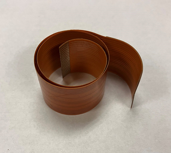
Figure 1. Clock spring flex-circuit designs can help facilitate electrical connections to rotating features in an electromechanical assembly.
Is the flex coil constrained by anything? The flex must be able to coil in and out without contacting any surfaces other than maybe along the edge of the flex. If there is an outer diametrical constraint where the flex makes contact and “bottoms out” before the shaft reaches the full 180° of range, there will be problems. If this is the case, another turn or two may be added into the coil length to minimize the amount that each turn in the clock spring is moving.
How fast is the shaft rotating? If the shaft rotates fairly quickly, stress may concentrate at the ends of the clock spring. Consider strain relief where the uniform run of the flex transitions to the connection. Options for strain relief would be semi-rigid epoxy or staggered lengths of thin polyimide near the last 0.5-1″ of length adjacent to the connection zone.
How many signals are there? The number of signals on the flex dictates the number of layers needed. As stated, a single layer design will give the best overall performance and longest life. If the design allows widening the flex to get all traces on one layer, do it.
Impedance requirements? If there are controlled impedance or electrical noise issues, shielding is needed. This, of course, will add thickness to the circuit, which is exactly what you don’t want. But if the circuit will not function without a shield on one or both sides, use shielding film instead of copper planes. Shielding films typically add less than 25µm per layer, thus the impact on overall thickness is minimal. Also, consider whether the shield is needed on both sides of the circuit. Since each turn of the “spring” will be near the other adjacent turns, there may be some noise benefit from those adjacent shields.
Final considerations. As you calculate the total overall length of the clock spring, keep in mind that the more turns there are, the less each must move to accommodate the 360° of motion. The downside is that more turns means filling up the cavity where the flex needs to be able to move without restriction. Additional length will also add cost, as the circuit footprint increases. While reducing the number of turns may save some money, it increases the risk the flex will become taut in the “wound up” configuration. Balance the length so that the flex will be in a relatively relaxed condition in both the “wound up” and the “unwound” positions.
Due to all the potential pitfalls you may encounter with a clock spring design, I highly recommend a chat with the flex supplier to ensure that all bases are covered. This will give the best chance of success on the first spin.
Mark Finstad is director of engineering at Flexible Circuit Technologies (flexiblecircuit.com); This email address is being protected from spambots. You need JavaScript enabled to view it.. He and co-“Flexpert” Nick Koop (This email address is being protected from spambots. You need JavaScript enabled to view it.) welcome your suggestions. They will speak at PCB West at the Santa Clara Convention Center in October.


