Several methods can be used to wrap a flex circuit around a tube, but most important is getting it to stay there.
Question: I want to wrap a flex circuit around a small diameter tube longitudinally and bond it in place. What is the smallest diameter tube I can wrap a flex circuit around?
Answer: The smallest diameter mandrel you can wrap a flex circuit around is driven mainly by the overall thickness of the circuit. The thinner the circuit, the smaller the mandrel diameter, with a hard stop somewhere between 0.150" and 0.250". The polyimide insulation material (used for outer covers and internal layer separation) is manufactured in a flat sheet, and that is the way it wants to stay. I’ve received numerous inquiries on this over the years (except they usually already have a mandrel size in mind). My quick answer is, assuming one single-layer circuit, 0.5oz. copper, and 0.001" polyimide top and bottom, the smallest diameter I would feel comfortable endorsing is about 0.25".
Now for the long answer. The smallest radius is also affected by how far around the mandrel you want to wrap the flex. The 0.25" diameter I mentioned assumes the flex is only wrapped 180˚ or less. The further the flex is wrapped, the larger the diameter will need to be. The internal forces in the flex circuit created when the circuit is wrapped will increase the farther around the mandrel the flex is wrapped. The end result is the edges of the flex will want to lift away from the mandrel after it is bonded.
I have used several methods to wrap a flex circuit around a tube, and just as important, stay there once wrapped.
Heat forming. This method is most effective, but also far and away the most costly. This method requires some pretty elaborate tooling to both form and hold the flex in place during the forming process. How far around the tube (i.e., 180˚, 360˚, etc.) you want to go will drive how many operations are required to complete the form. The tube the circuit is to be formed around is generally an integral part of the forming operation. A combination of the methods below could probably be used to preform a flex and have it stay in a standalone cylindrical shape, but be advised the road to that end will be rocky.
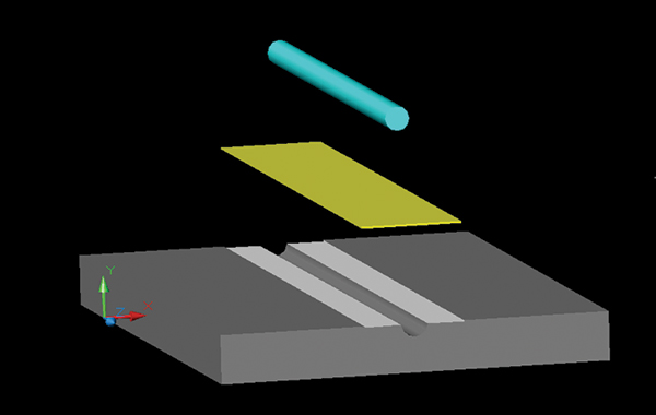
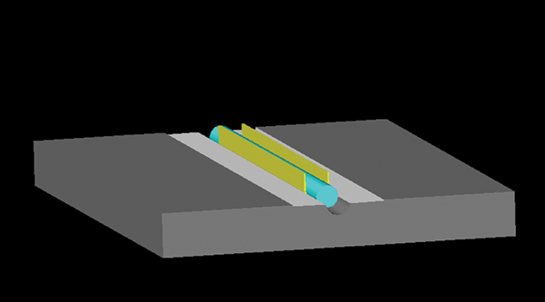
The first step in heat forming is to create the tooling. The first tool is usually a flat metal plate with a half round groove cut out (diameter of mandrel + flex thickness + a few extra mils). This plate will also require some registration features that will allow you to position and hold the flex over the groove accurately during the forming process. The flex is placed over the groove, and then the mandrel is pressed into the flex, which forces it into the groove (FIGURES 1 and 2). The assembly now needs to be heated to ~250˚F+ and then cooled while constrained in this condition. The next step is to complete the form with a top plate that mirrors the bottom plate. The top plate with mating groove is placed over the bottom plate and pressed until the plates are in contact with each other (FIGURE 3). Then the whole assembly is again heated to ~250˚F+ and cooled to room temperature while constrained. The result is a flex that will hold most of the form and allow a shrink tube to be placed over the entire assembly to hold it in place permanently.

Figure 1. The bottom plate with forming groove, the flex (yellow rectangle), and the tube the flex will be formed around.

Figure 2. The flex pushed into the forming groove by the tube. The flex must be constrained in this position when heated and cooled.

Figure 3. The addition of the top forming plate. The two plates must be clamped together as the assembly is heated and cooled.
If the application does not permit the extra thickness of the shrink tube around the assembly, the flex can be bonded to the tube with a pressure sensitive adhesive (PSA). If the flex must be wrapped more than 180˚ (requiring two forming steps), “kiss” cut the release liner on the PSA to permit removal of only the center strip of release liner for the first forming operation. If wrapping 180˚ or less, the flex may be laminated to the tube with thermosetting adhesive. This will give far superior peel strength over PSA. Unfortunately, thermosetting adhesive is usually not a good choice for forms of 180˚+ because the heat from the first forming operation may cure the adhesive needed to bond on the second operation.
Spiral wrap. One other method I have seen used is a spiral wrap pattern so it looks like a barber pole. A narrow flex backed with PSA is wrapped up the mandrel in a spiral pattern. This type of form can usually be done by hand if the radius is reasonable. The downside is the flex can end up being really long, and this equates to really expensive!
Mark Finstad is senior application engineer at Flexible Circuit Technologies (flexiblecircuit.com); This email address is being protected from spambots. You need JavaScript enabled to view it.. He and co-“Flexperts” Mark Verbrugge (This email address is being protected from spambots. You need JavaScript enabled to view it.) and Nick Koop (This email address is being protected from spambots. You need JavaScript enabled to view it.) welcome your suggestions.
Register now for PCB West, the Silicon Valley's largest trade show for the printed circuit industry, taking place Sept. 13-15 in Santa Clara: PCBWEST.COM


