Page 3 of 4
Groups. Items can be assigned to groups in IDX, a capability not supported by the IDF. For example, a component can be grouped with a route keep-out. Or, the components that comprise a related portion of a circuit in an area of the board can be grouped.
Constraints can be assigned to a group to determine the behavior of the group, for example, that the items in the group have to move or rotate as a unit. A group can also have an owner that specifies who is responsible for the group.
Text. As with IDF 3.0, IDX provides support for displayable text that can be used to annotate a design but is not part of the design itself. However, IDX allows more control over the size and appearance of text. Each occurrence of IDX text is located within a bounding box defined by upper left and lower right points, and can specify a font, style, weight, alignment, and other attributes.
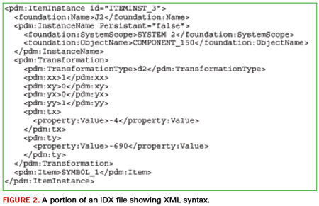
IDX files are XML documents, so their syntax is XML syntax. The structure of an IDX file is defined by a dozen interrelated XML schemas that comprise the EDMD data model.
Every IDX file contains a root element with a Header section followed by a Body section. The Header contains general information about the file, such as the creator of the file and the tool that was used to create it. The Body section includes all the information – shapes, items, instances, properties, groups, roles, etc. – that describe the current state of the design.
IDX files that represent a complete design state, called baseline files, tend to be large – at least an order of magnitude larger than corresponding IDF files. Large designs can result in IDX files several megabytes in size. However, IDX files that represent incremental design changes are generally much smaller, depending on the number and nature of changes they contain.
Note that IDX files are not designed to be edited by hand. Many of the XML elements in an IDX file contain references to other XML elements in the file. Modifying or removing portions of the file can result in incorrect design information or even corrupt the entire file. IDX files should only be processed by applications that comply with the EDMD data model.
Figure 2 is a small excerpt from the Body section of an IDX file that defines a component instance.\

Managing Change
IDX’s most significant contribution to ECAD/MCAD collaboration is its ability to represent and manage incremental changes throughout the design cycle. This lets designers focus on what’s most important as the design evolves, and collaborate on the changes.
The key to incremental exchange is having unique, persistent identifiers for each design object. With the IDF, only component instances have unique identifiers – their reference designators. In IDX, every item definition and item instance has a unique identifier. So, for example, if a keep-out is removed from the mechanical design and an IDX file is sent with this change, the receiving ECAD system knows which keep-out to remove in the layout by its matching IDX identifier. As another example, having unique identifiers for component instances permits reference designators to be re-sequenced for manufacturing purposes at the end of the design process.
The identifiers are established and communicated in a baseline IDX file exchange. The baseline file sets the initial state of the design and is the starting point for future collaboration. The baseline can come from either CAD system. Often, this is MCAD, where the mechanical designer determines the board shape, mounting hole locations, and the locations of critical components such as connectors and switches. Or, if a new design is based on an existing design, the baseline may come from ECAD.
After the baseline exchange, both CAD systems have the same identifier for every design object exchanged in the baseline, and the mechanical design and PCB layout are synchronized from a collaboration standpoint. Subsequent IDX file exchanges contain only objects that have changed from the baseline or from a later synchronized state of the design.
An IDX change file contains a Changes section that specifies what items and item instances have changed, with references to the actual changes described in the Body section. Changes can result from adding new items (such as placing new components on the board), moving items (such as relocating a mounting hole), modifying items (such as changing the board shape), or deleting items (such as removing a keep-out).
IDX can also indicate the acceptance state of changed items. This allows designers to preview proposed changes and either accept or reject them. The accepted and rejected changes are communicated through another IDX exchange back to the sending system so that the state of the mechanical design and PCB layout can be kept in synch.


