
Routing high pin count BGAs contributes to increased layer count, but maximizing route density by region using blind and buried vias can reverse the trend.
This article presents a new concept in applying different types of fanout patterns for BGAs by specific region. The figures in this article show the overall view of the BGA and the regions, along with detailed views of the fanout pattern in each region.
The reason for using regions is to get the most effective fanout patterns based on the available via spans and layer stackup. The idea is to fan out with layer 1:2 and 1:3 blind vias around the perimeter of the BGA using an aligned-via pattern (described in detail in previous articles) thus effectively reducing the size of the BGA that must be routed using buried or through-vias.
This technique can be applied when blind and buried vias are available. The exact pattern used in each region will likely vary depending on the balance of the route density, signal, and power integrity requirements. The fanout patterns and the regions in this example focus on maximizing the route density. We will look various patterns based on the stackup and via spans in Figure 1 and demonstrate how variable depth microvias can be used.
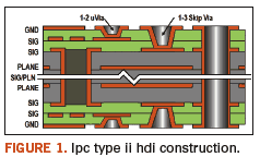
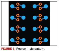
Region 1 comprises the outer rows. The number of rows will vary from 4 to 6, depending on the design rules. As shown in Figure 2, this region uses a 1:2 microvia with the intent of routing the traces on Layer 2 at maximum route density. This pattern can be varied by moving the via closer to the ball pad and changing the angle, so that the via spacing exceeds the minimum. If you do this, the route density will decrease; however, you may increase room for plane fill and reduce potential crosstalk between the vias.
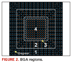
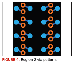
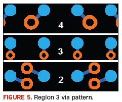
Region 2 includes all the inside rows. Once the outer rows of BGA pins are routed using the 1:2 micro-vias, the next 4 to 6 rows should use the 1:3 skip-vias, with the intent of routing the traces on Layer 3 at maximum route density, as shown in Figure 3. Using the skip-via allows a connection from Layer 1 to Layer 3 without a pad on Layer 2. This pattern can also be varied by moving the via closer to the ball pad and changing the angle so that via spacing exceeds the minimum.
Region 3 is the transition between the inside rows (Region 2) and the center rows (Region 4). Since the patterns between Regions 2 and 4 will usually conflict and cause DRC violations, a transition area is appropriate. Figure 4 shows a useful pattern for the transition area. A 1:2 or 1:3 via can be used in the transition area depending on your routing strategy. In this example, the pattern is a simple orthogonal short dog-bone. Other angles may be used depending on the via size used.
Region 4 is the center. The center rows are those left over after other regions have been defined. Usually, the center of the BGA has power and ground pins, and thus putting the through vias in a standard dog-bone pattern as shown in Figure 5 makes sense. Note that the vias are not located in the exact center of the ball pad matrix – this allows for a greater ground plane fill on Layer 1.
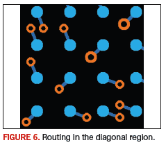
The Diagonal Region. The pins along the diagonals could have conflicting patterns when the Region 1 and Region 2 fanouts merge. The example in Figure 6 shows a method that not only merges the patterns, but also spreads the vias away from the centerline, providing greater route density along the diagonal.
Dividing up the BGA into regions enables maximum route density, and can thereby reduce the number of layers needed. When the BGA has over 1500 pins, simply routing out of the BGA tends to be the primary contributor to increased layer count. By varying the number of rows used in each region, based on the stackup and via spans available, you can obtain the most optimal fanouts and routing in the context of your own specific design. PCD&F
Charles Pfeil is an engineering director for Mentor Graphics, Systems Design Division. He can be reached at This email address is being protected from spambots. You need JavaScript enabled to view it.. Go to www.mentor.com/go/bga to obtain a copy of Charles Pfeil’s new book, “BGA Breakouts & Routing.”


