Return and insertion loss are frequency domain concepts that are quickly becoming mainstream terms in the high-speed digital world.
Twenty years ago, in the good old days of 20 MHz clocks, interconnects were transparent and only the “bleeding edge” users insisted on controlled impedance boards. Now, everyone needs controlled impedance boards, whether they specify them or not.
Ten years ago, in the good old days of 200 MHz clocks, all busses were parallel and single ended. Only the bleeding edge users cared about differential pairs. Now, with the introduction of SATA drives and PCI-Express in PCs, all motherboards, and most other products need differential pairs, whether they specify them or not.
Now, with clocks in excess of 2 GHz and data rates of more than 5 Gbps becoming mainstream, losses in interconnects begin to dominate performance and must be considered in the board design.
With each new layer of the high performance onion peeled back, new vocabulary, new design principles, and new characterization and test methods must be adopted by the printed circuit design and manufacture community to provide cost effective products that meet the new specifications.
For controlled impedance boards, we needed the principles of characteristic impedance and TDR to verify specs. For differential boards, we needed the principles of differential impedance and differential TDR to verify specs. In the regime of high-speed serial links, well into the Gbps rates, we need a new set of vocabulary, new design principles, and new characterization and test methods. These are not new to the bleeding edge users, but they are new to the mainstream.
Return loss and insertion loss are two of the new terms that will be used more and more by the mainstream to characterize and describe the performance of interconnects in the GHz regime. And, a new online simulation tool has become available to help you explore these new terms to help build your intuition.
Return and insertion loss are frequency domain concepts borrowed from the microwave world that are quickly becoming mainstream terms in the high-speed digital world.
|

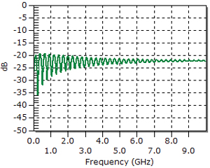
FIGURE 1. Simulated return loss of 12-inch long microstrip.
|
Return loss is the fraction of sine wave that reflects back from an interconnect in the special case when the source driving it and the far end termination are each 50 ohms. The more transparent the interconnect, the less that reflects and the smaller the return loss. When measured as a dB, a really small magnitude means a large, negative dB. The larger the negative dB magnitude is, the more transparent it is. A typical, acceptable return loss is about -20 dB. Figure 1 shows the simulated return loss of a 7-mil wide microstrip, 12 inches long with a characteristic impedance of about 42 ohms.
|

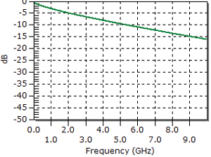
FIGURE 2. Simulated insertion loss of the 12-inch long microstrip.
|
The insertion loss of an interconnect is the fraction of sine wave amplitude that is transmitted through it, also when it is driven by and terminated in 50 ohms. A transparent interconnect will have 100% of the sine wave transmitted, or an insertion loss of 1. In dB, 1 is 0 dB. As the insertion loss drops, less signal is transmitted and the value in dB will become a larger negative dB. Figure 2 shows the simulated insertion loss of this microstrip.
|

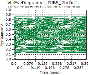
FIGURE 3. Simulated eye diagram of a 5 Gbps PRBS pattern through a 30-inch segment of the microstrip above.
|
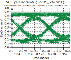
These calculations and plots are just a few of the many simulations you can experiment with on a new online calculator tool written by Tom Clupper and graciously made available by W.L. Gore. You can visit their web site, TlineSim.com and explore return and insertion loss of microstrips, striplines and coaxes, compare the time domain step response and frequency domain response and even look at what an eye diagram of a PRBS, through an interconnect, might look like. With three mouse clicks, the eye diagram of a 30-inch long version of the microstrip above was simulated (Figure 3) and in one mouse click, the improvement when adding 50% pre-emphasis was simulated (Figure 4).
|

FIGURE 4. Same interconnect as above, but with 50% pre-emphasis on the signal.
|
This is a rich site for introducing yourself to the new world of return and insertion loss and the behavior of interconnects in the GHz regime.
To get you started with this new tool, I’ve also prepared a free online lecture, OLL-030 Return and Insertion Loss for Dummies, posted on my web site, BeTheSignal.com. Happy trails. PCD&M
This and other topics are covered in the public classes Eric teaches. Check his web site for the schedule: BeTheSignal.com. Send questions to This email address is being protected from spambots. You need JavaScript enabled to view it..
Dr. Eric Bogatin is president of Bogatin Enterprises.


