Graphite systems coat and then bind to resin and glass, making them
ideal for use with a wide variety of high performance laminate
materials.
While the interest in alternative metalization processes for the manufacturing of printed circuit boards is extremely keen, there is even greater interest today with respect to the requirement for lead-free and high performance laminates. It is well documented that these higher performance materials are much more difficult to desmear due to the materials’ enhanced chemical resistance. These materials resist permanganate attack more than the low Tg materials. This resistance often reduces the adhesion and coverage of electroless copper. This is compounded by the fact that many fabricators today are competing on both time and technology. That is, these firms are offering the capability of building printed circuit boards based on multiple material sets, including liquid crystal polymer, ceramic filled materials, polyimide, flex and a variety of other high performance and lead-free laminate materials.
Most fabricators do not have the luxury of multiple permanganate cycles that would mitigate the effects of the different material sets. Thus, there is a need for a reliable process that has the capability to metalize these resin surfaces, regardless of the material type and without optimal desmear. The purpose of this article is to present an overview of an enhanced patented graphite-based direct metallization system. A second objective entails a detailed description of the technology behind the graphite dispersion system and its adhesion mechanism to different resin materials.
Description of the Graphite-Based Direct Metalization Process
The process described herein is based on a very fine and stable aqueous dispersion of graphite. The graphite particle, by virtue of its crystalline structure, is highly conductive and has been demonstrated to enable the uniform electrodeposition of copper from acid sulfate electrolytes. And, despite earlier setbacks associated with the use of graphite, significant advances in the overall process and in the dispersion itself has rendered the process viable for the metalization of plated through-hole multilayer and double-sided printed circuit boards. Earlier problems such as voids on the resin and occasional poor adhesion have been eliminated. Anionic dispersion agents aid in maintaining the stability of the graphite suspension. And an additional benefit of the process is its ability to coat and render conductive a wide variety of resin materials cutting across multiple applications including telecom, mobile computing, automotive and military.
Cleaning and Conditioning
This process step is critical in preparing the glass and resin to receive the graphite dispersion. The slightly alkaline chemistry contains a cationic polyelectrolyte with multiple positive charges. The highly charged polyelectrolyte provides a net positive charge on the glass and the resin, aiding in the electrostatic attraction of the graphite particle. It is apparent that such a mechanism of adhesion is indifferent with respect to resin or material type.
Graphite Conductive Colloid
After cleaning and conditioning the glass fiber bundles and the resin (or in some cases, non-glass reinforced material such as flex or resin coated copper) a room temperature rinse follows. Then, the substrate is treated with a specialized dispersion of graphite. The graphite is highly conductive and suitable for subsequent metalization of plated through-hole printed circuit boards. The graphite is dispersed in an aqueous medium with a pH in the range of 8.5 to 9.6. The choice of graphite may be either a synthetic or naturally occurring entity. For reasons of superior conductivity, synthetic graphite is preferred.
Graphite is often compared erroneously to carbon black, a semi-conductive form of carbon. Carbon black is the main ingredient of another direct metalization system. When one compares the structure of these two forms of carbon, one notes that graphite has a highly crystalline structure, while carbon black is amorphous. The crystalline structure enables the graphite to have higher conductivity than carbon black, which is a significant advantage in electroplating small holes in very thick printed circuit boards.
Another key component of the graphite dispersion is the inclusion of a water-soluble binding agent. The binding agent is designed to coat the graphite particles and aid the particles in adhering to the hole walls of the plated through-hole printed circuit board. The water-soluble binding agent can be selected from a variety of polymers, resins and other acrylate compounds. It is important to recognize that this interaction, that of the resin/conditioner with the binder of the graphite, is critical. This interaction does not require a highly roughened surface, nor does it require a sufficient amount of manganese dioxide to act as a catalyst as some direct metallization systems require. This especially adhesive mechanism is what allows the graphite process to adhere to a variety of different materials and resins1.
An anionic dispersing agent is added to the graphite dispersion. The preferred agent would have a molecular weight less than 1,000 Daltons so that it is substantially smaller than the binder agent. The anionic dispersing agent has a hydrophobic end and a hydrophilic end. The hydrophobic end functions by attracting the hydrophobic region of the binding agent, while the hydrophilic (anionic end) portion of the dispersing agent sticks out into the aqueous region the water medium. This action helps to prevent the graphite particles from being attracted to each other and forming some type of agglomeration. In addition, the negative charges surrounding each bound graphite particle provide the attractive forces that allow the particles to adhere to the positively charged resin and glass bundles. As was disclosed earlier, the cationic polyelectrolyte, a key ingredient in the cleaning/conditioning step, coats the glass and resin, providing a very high positively charged surface1.
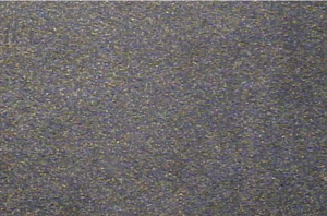
The resulting composition of the aqueous dispersion of graphite is capable of depositing a uniform, adherent and highly conductive coating on the non-conductive surfaces of the substrate. In Figure 1 the graphite dispersion is shown coated on a highly polished glass surface. The coating is uniform and tightly bound, thus enabling the deposition of copper in a subsequent step.
|

FIGURE 1. Graphite dispersion coated and dried on polished glass slide (normal colloidal graphite)
|
As we have learned from extensive testing and reliability data, the fixer step is probably the most important and critical aspect in producing highly reliable vias and through vias. The fixer is a proprietary acidic solution that is used at typically 120?±5?F. The fixer provides protons (hydrogen ions) to neutralize the anionic charged binder surrounding the graphite particles.
Once the charge is neutralized the colloidal graphite becomes insoluble so only a thin, tightly coherent coating is left, which is attracted and partially polymerized to the conditioner. Due to the action of the fixer on the binder, the excess neutralized colloidal graphite is rinsed away and the insoluble, partially polymerized conductive coating is left behind. Secondly, the fixer step acts to further enhance the adhesion of the graphite to the organic resin and glass reinforcement. Once the excess coating has been removed, the drying step is applied. This step is critical in that the drying will drive out any excess moisture from the partially polymerized graphite coating. The coating now becomes completely polymerized. This step leaves a very conductive pathway through the PTH and microvia, thus enabling the electrodeposition of copper to take place.
The fixer step is critical in that excess graphite could remain on the face of the copper interconnect or on the capture pads of small blind vias. This is most critical for long-term thermal reliability of plated through-holes and microvias. Fixer ensures no excess material remains, compromising interconnect integrity.
After the fixing step, a cold-water rinse is employed, followed by a drying step. The drying step serves to remove the water from the coating, thereby making the coating inert to subsequent processing conditions. After drying, a microetch solution containing persulfate or hydrogen peroxide- sulfuric acid is utilized. The purpose of this step is to undercut the coating by etching the copper underneath. This allows the dried graphite to be removed from the copper clad outer surfaces and the interlayer connections. Since there is no copper where there is glass and resin, the coating remains intact.
Enabling the Electrodeposition of Copper
The critical success factors that enable the electrodeposition of copper to non-conductive substrates are the fine graphite particle size and the uniformity of the graphite coating as shown in Figure 1. A second principle involves the ability of the coating to conduct current with minimal resistance through the via. The resistance of a printed circuit board is an indication of the time it will take to electroplate the through-holes. The lower the resistance, the faster the propagation rate of the electrodeposition process. Typically, when the resistance of a multilayer printed circuit board is measured by conventional means, the graphite process yields resistance values after microetching at less than 300 Ohms. More typically, these measurements are in the 30-35 Ohm range. This low resistance enables the electrodeposition of copper to proceed at optimum propagation rates, minimizing the through-hole tapering effect often seen with other types of direct metallization systems.
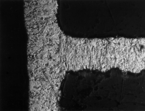
In Figure 2 the microsection shows a polished and etched specimen that has been metalized with a graphite-based direct metallization system. IST, thermal shock and thermal stress testing data support the fact that the electrodeposited copper to foil bond is of the utmost reliability2.
|

FIGURE 2. Note the copper-to-copper bond of the interconnect foil to the electrodeposited copper when processed with graphite-based direct metallization. There is an absence of a line of demarcation (CuCI2/NH4OH etch).
|
The Laminate Performance Pyramid
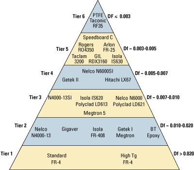
One cannot escape the fact that the interconnect industry is moving up towards the apex of the laminate performance pyramid. The laminate performance pyramid (Figure 3) is a graphical depiction of the material types that are finding increased use for IC packaging and high-speed, low-loss constructions. Tiers 3 and 4 will be required for future generations of high-speed digital broadband, and Tiers 5 and 6 will be included for RF and microwave technologies. There is an extensive range of PTFE materials for this market. More North American and European fabricators will be building PCBs with these materials. There are applications now where Tier 5 and 6 materials are used as signal layers along with power and ground layers of Tier 3 and 4 materials. This is truly a mixed package of materials that increases the degree of difficulty with respect to desmear and metallization3.
|

FIGURE 3. Laminate performance pyramid.
|
Why be concerned with the different laminate materials? Aside from the obvious, successful metallization requires that excellent adhesion between the conductive coating (either electroless copper or conductive graphite) be achieved. It is well documented that adhesion is favored when there is sufficient surface topography to promote the bond. This is especially true for electroless copper as the seeding of the palladium required to initiate the copper deposition is enhanced through a micro-roughness of the surface. In addition, the micro-roughness further enhances the adhesion of the electroless copper to the base metal surface.
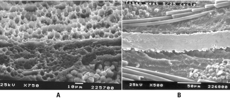
However, as one views the SEM in Figure 4 the topography visible after permanganate desmear is rather smooth and unremarkable, further impacting the adhesion factor. On the other hand, the graphite-based system coats and binds to resin and glass without the need for a high surface area. It is important to recognize that electroless copper is a plating process whereby a series of reactions take place in order to affect a deposit. In the case of the graphite-based metallization system presented herein, the mechanism is primarily a coating process. To place the discussion in the proper context, the SEMs in Figure 4 depict two different materials that have been desmeared with an alkaline permanganate system. The lower Tg material is pictured on the left (Figure 4a), and the higher performance material is depicted on the right (Figure 4b).
|

FIGURE 4. a) Tier 1 resin material after alkaline permanganate desmear. b) Tier 4 material after alkaline permanganate desmear.
|
The direct metalization system based on a conductive graphite dispersion has gained acceptance throughout the world as an environmentally sound, cost effective and reliable alternative to electroless copper. On the issues of compatibility with a variety of high performance resin materials, the graphite metallization process is designed to coat these materials without the benefit of high surface topography. The mechanism for the adhesion of the conductive graphite coating to these different materials has been described herein. PCD&M
Michael Carano is vice president, marketing and business development at Electrochemicals Inc. He can be reached at This email address is being protected from spambots. You need JavaScript enabled to view it..
REFERENCES
1. U.S Patent # 5,476,580
2. “Printed Wiring Board Cleaner Technologies Substitute Assessment: Making Holes Conductive,” U.S. EPA Publication, Washington, D.C.
3. World Wide Market Trends in High Speed Laminate, BPA Consulting, LTD. 2006.


