When taking measurements or doing simulations, it’s good to anticipate your results ahead of time.
Question from Scott in Tucson, AZ: Everyone says that if you bring a grounded trace next to a signal line, the impedance of the signal line will drop. This is because of the proximity of the ground next to the signal line. If this is true, is there a rule of thumb to use to estimate how the impedance of a line is affected by the proximity of an adjacent signal line?
Answer: I think this is another myth. And while there is always a basis of truth in each myth, it is dangerous to apply sweeping generalizations. After all, the most common answer to every signal integrity question is, “It depends,” and the only way to know if it depends in yoour specific case is to plug in the numbers.
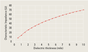
In this example, we will put in numbers using the built-in 2D boundary element field solver in Agilent’s ADS. We can use this tool, as well as other 2D field solver tools, to calculate the characteristic impedance of one transmission line in almost any geometrical configuration. Let’s start with a simple microstrip with a line width of 10 mils, dielectric constant of 4.5 and thin metallization. Using ADS, we can sweep the dielectric thickness, plot the extracted characteristic impedance and find the thickness for a 50-Ω microstrip (Figure 1).
|

FIGURE 1. Sweeping the dielectric thickness to find the optimum value for a 50-Ω microstrip.
|
With this optimized dielectric thickness of about 5.3 mils, we gradually bring a second trace, also 10 mils wide and grounded on the ends, in proximity and calculate the characteristic impedance of the first trace as the separation changes.
As a general rule, you should never perform a measurement or simulation without first anticipating what you expect to see. If you are right, you have a good intuitive feel for the problem. If you are wrong, either your intuition is off or the problem is not configured as you think. Either way, you will learn something new and advance along the learning curve. And when you do this a lot, you find this continual testing of your intuition is fun. So, what would you expect to see?
When the grounded trace is far away, there should be no impact on the impedance of the first trace. As they are brought in proximity, the grounded trace should increase the capacitance to ground of the signal trace, thereby lowering its impedance. But by how much?
|

FIGURE 2. Fringe fields from a microstrip trace with an adjacent grounded trace.
|
When the traces are far apart, there are fringe fields from the first trace to the ground plane. When the adjacent ground trace is brought close, it will intercept these fringe fields, but they will also go to ground (Figure 2).
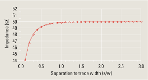
The proximity of the adjacent ground trace should not have a strong impact on the signal trace. A quick way to find out is with a 2D field solver. The calculated impedance of the trace, as we move the ground trace closer, is shown in Figure 3.
|

FIGURE 3. Calculated impedance of the signal line as the grounded adjacent trace is brought in proximity, compared to the ratio of the separation to the line width.
|
The proximity of the grounded second trace really does decrease the impedance of the signal trace, and it drops it more as the ground trace gets closer. However, the effect is very small. As long as the adjacent trace is at least a line width away, it has an impact of less than 0.1 Ω on the impedance of the line. When it is within half a line width away, the impedance drops by 1 Ω, and then drops faster as the ground trace gets closer.
In most applications, an adjacent ground trace is at least 1 line width apart. This analysis suggests a simple rule of thumb: There is no impact on the impedance of a 50-Ω microstrip signal line as a grounded trace is brought adjacent to it. This rule of thumb also applies to stripline. PCD&M
This and other topics are covered in the public classes Eric teaches. Check his Web site for the schedule: BeTheSignal.com. Send questions for the Signal Doctor to This email address is being protected from spambots. You need JavaScript enabled to view it..
Dr. Eric Bogatin is president of Bogatin Enterprises.


