How to ensure documentation for the EMS company is accurate.
Electronics assembly documentation includes files such as design schematics, assembly drawings, test procedures, bills of materials and more. Problems or omissions in this documentation result in delays and, in extreme cases, may lead to product deficiencies and quality issues. The following best practices will help ensure that documentation to be sent to the EMS company is in good order.
Documentation is typically provided to us in a .zip file that contains documentation related to details of the PCB, assembly work required, materials required, design schematics, test procedures, special instructions, and more. Ideally, the documentation files should be separated into discrete folders. As an EMS company, we prefer either:
- A distinct .zip file for each type of data (e.g. schematics, bill of materials, assembly, test), or
- One .zip with an embedded directory structure that keeps these types of data discrete.
The following are common errors related to manufacturing documents. Avoiding these errors will improve delivery time and quality.
CAD data. Not every contract manufacturer has the systems to handle CAD data. For those that do, accurate CAD data improve information flow and can reduce manufacturing time and design errors. For example, the manufacturer can query CAD data for accurate dimensions and other product details.
If using a third party for CAD layout, request the CAD layout data from that company. If producing CAD layouts in-house, follow these guidelines:
- ASCII CAD is the preferred data format. ODB++ and GenCAD are acceptable alternate formats.
- Ensure the correct version of the data is sent. Double-check the version, or rely on a rigorous documentation control program to ensure the correct versions are employed.
- Send Gerber data in only one format, rather than multiple formats. At many firms, RS-274x is the preferred format for Gerber data.
- Verify that the aperture data you send are correct; documentation sometimes contains aperture dimensions of “0”, requiring the CM to halt the process and request clarification.
- Avoid sending redundant data, such as sending both Gerber files and apertur data containing aperture data separately. RS-274x Gerber files already contain the aperture data.
- In the Gerber data or a separate PCB document, include specifications for copper weight, surface finish and laminate.
Schematics and drawings. Adhere to these three best practices when preparing schematics and drawings for a contract manufacturer:
- Include PCB schematics. These tell the contract manufacturer how parts on a board are to be connected. CMs refer to these drawings to ensure interconnect is accurate and to solve problems, if they arise. EDIF format is preferred because an EDIF file carries intelligence that can be cross-referenced with CAD data and assembly drawings to speed debugging. PDF format is also acceptable, but does not contain intelligence. If the contract manufacturer will perform testing, providing a schematic is essential for debugging.
- Include assembly drawings in the documentation package. An assembly drawing provides higher-quality information about board assembly than Gerber data.
Reference a workmanship standard to which the manufacturer must adhere. If special assembly steps or requirements exist, indicate these on the drawing. PDF format is acceptable for assembly drawings.
Bill of materials. Follow these guidelines when preparing BoMs for the contract manufacturer:
- Send a BoM in only one file format. A spreadsheet is preferred to a text or PDF file.
- Always include alternate parts in the BoM, as this ensures the benefit of lower pricing or reduced lead times on parts.
- Always include complete manufacturer part numbers in the BoM; not doing so can cause delays.
Functional specification. A functional specification of how the product is meant to function is helpful if testing is being undertaken. This information cannot be conveyed by a schematic or CAD data. A functional specification should describe how the product is designed to work and its acceptable limits. This, in combination with the other documentation, allows technicians to understand the product quickly and move on to efficient testing and debug.
George Henning is vice president of manufacturing at OCM Manufacturing (www.ocmmanufacturing.com); This email address is being protected from spambots. You need JavaScript enabled to view it..
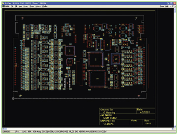
Figure 1. Working from the CAD system offers the best chance at accurate data.
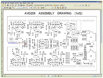
Figure 2. The assembly drawing provides higher-quality information about board assembly than do Gerber data and should
be included.


