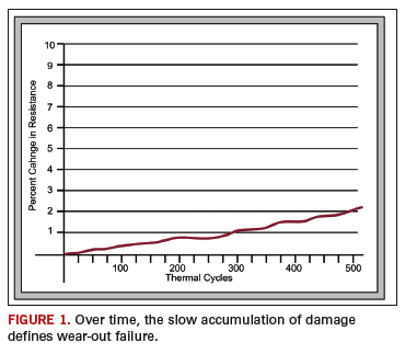
Slow increases in resistance during testing suggests metal fatigue, or wear-out failure, a common failure mode for robust PCBs.
When exposed to thermal cycle testing, cracks that develop slowly in the copper barrel of plated through holes (PTHs) are considered to be a wear-out failure mode. This is the failure mode of robust PCBs, often observed in boards that survive hundreds, or thousands, of thermal cycles. There is an initiation of cracks in the barrel of the PTH that can advance through the metallization and the electrodeposited copper layers. The cracks typically propagate along the boundary between copper crystals and traverse the thickness of the barrel in a tortuous path. They usually initiate at glass fibers that are on the inner edge of the drill hole and frequently have an angle 30° to 50° off horizontal. Once initiated, the cracks slowly develop over hundreds of cycles, and the damage accumulates at a constant rate.
It is possible to create a graph to chart the damage accumulation during thermal cycle testing. This is done by plotting the resistance, taken at the maximum test temperature, for each cycle. The measurement of the first thermal excursion, at the maximum temperature, establishes the baseline condition against which subsequent measurements are compared. A 10% increase in resistance, typically measured in milliohms, is considered a failure. The y-axis shows resistance, with the top of the graph indicating a failure at a 10% increase in resistance; the x-axis variable is the number of thermal cycles.
Plotting a resistance graph of damage accumulation allows one to determine onset, rate of accumulation and if the damage is accelerating. Different failure modes tend to produce different damage profiles. Armed with a resistance graph and cycles-to-failure data, insight on the failure mode can be gained. Degradation of copper and material, as well as stress relief, may be inferred by the damage profile.
FIGURE 1 demonstrates the initial damage occurred at the beginning of testing, an progressed with a constant accumulation of damage throughout the life of the test. This damage profile is typical of wear-out failure. A constant, slow accumulation of resistance over the duration of the test suggests metal fatigue.
Frequently, cracks are in the central zone of the PTH barrel. During thermal excursions, the PTH is under tension from z-axis expansion. Above the glass transition temperature (Tg), the coefficient of thermal expansion (CTE) in the z-axis is typically around 150 ppm/°C to 350 ppm/°C. The x-axis and y-axis compression of the copper barrel is approximately 20 ppm/°C to 40 ppm/°C above Tg. The warp and the weft of the glass fiber restrain thermal expansion in the x- and the y-axis. The direction of the fiberglass warp exhibits a slightly lower CTE than the weft direction.


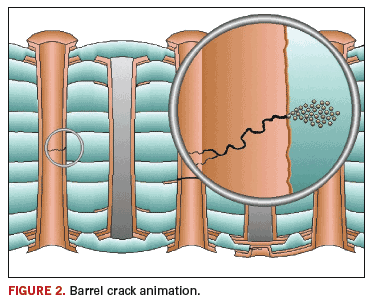
Observe in
FIGURE 2 that the greatest x/y inflection of the PTH is in the central zone of the barrel. It is likely that the compressive forces to the central zone of the PTH, occurring while it is under tension from z-axis expansion, apply localized stresses, allowing cracks to be expressed in that area. It should be noted that the material appears not to degrade and remains, to some degree, elastic throughout the life of the test.
PCD&FPaul Reid is program coordinator at PWB Interconnect Solutions Inc.;
This email address is being protected from spambots. You need JavaScript enabled to view it..


