At high frequencies the return current follows the path of least inductance, not the path of least resistance.
It is well known and understood that at high frequencies return currents will find the path of least impedance to return to their source. What may not be well understood is where frequencies become ‘high frequencies’!
In reality, return current will always follow the path of least impedance. At lower frequencies, this means the path of least resistance and at high frequencies, this means the path of least inductance. The change over frequency can be surprising low.
A simple example to illustrate the change over frequency calculation can be obtained using a simple microstrip trace over a ground-reference plane on a PCB.
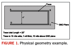
Figure 1 shows a microstrip over a reference plane and the dimensions for a U-shaped trace. The source is at one end, and the load at the opposite end of this U-shaped trace. At very low frequencies, it is expected that the return current will go straight across from the load to the source without traveling under the microstrip trace. At very high frequencies, it is expected that the large loop area formed by points A? B ? C ? D ?A will have very high impedance, and the return current will return under the trace. Even though the path for the return current under the trace is longer than the low frequency path, the loop area is smaller, hence the inductance (and impedance) is lower with the path A? B ? C ? D ? C ? B ? A.

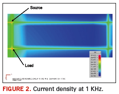
Figure 2 shows the current density on the PCB at 1 KHz. The current is seen to travel along the trace and then cut straight back to the source across the ground-reference plane.

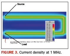
When the frequency is shifted to 1 MHz, the currents travel a very different path. At this frequency, the return currents do not travel directly from the load to the source, but rather travel along under the trace (Figure 3). While this is a much longer path than used in Figure 2, the inductance is much lower, and therefore the impedance is lower.

At 50 KHz some of the return current takes the direct (shortest) path and some of the return current takes the longer, lower inductance path.
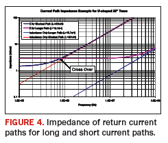
The inductance of these two paths can be calculated using a very rough approximation from the rectangular inductance formula given in Equation 1. While this formula looks intimidating at first, it is actually fairly simple to program into a spreadsheet. When using this formula, we calculate the inductance of the shorter path (low frequency path) to be 491 nH, and the inductance of the longer path (high frequency path) to be 10.7 nH. The DC resistance of the trace is calculated as 1.45 ohms, and a rough estimation of the long path resistance is twice the trace value (~ 3 ohms).

Figure 4 shows a calculation of the magnitude of the impedance for the inductances as well as the combined impedance for the resistance and inductance. Since the return current will always follow the path of least impedance, the cross over frequency is 800 KHz in this example. Below 800 KHz, the return current will take the shortest path, since it has the least resistance. Above 800 KHz, the majority of the return current will follow the longer path because it has less inductance.
The return current path will always find the path of least impedance. This impedance can be calculated to a first order approximation with a simple rectangular loop formula and the cross over frequency found quickly. PCD&F
Bruce Archambeault, Ph.D. is an IBM Distinguished Engineer and IEEE Fellow. He can be reached at This email address is being protected from spambots. You need JavaScript enabled to view it..


