Using sheet resistance as a metric can help you calibrate your intuition, even on structures such as vias.
Our intuition suggests that, generally, when conductors get longer,
their series resistance increases. In a very special case, this is not
true and is the basis of an important quality of all PCB copper layers.
Take
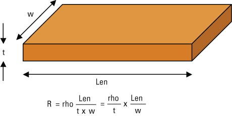
a 10-mil wide copper trace on a circuit board. The series resistance is
easy to calculate. It is the product of the bulk resistivity, usually
called rho, the Greek letter for r, and the length of the trace,
divided by the cross section area the current flows through, which is
the width of the trace and the thickness. This is illustrated in Figure 1.
|

FIGURE 1. Series resistance of a trace.
|
The bulk resistivity of copper is 1.7 x 10⁻⁸ Ohms-m, which is also 1.7 microOhm-cm and also 0.67 microOhm-inch.
This
matches our intuition that the longer the trace, the higher the
resistance and the larger the cross section for current to spread out,
the lower the resistance.
If we pick the special
geometry of the width of the trace exactly equal to the length of the
trace, we end up with a trace that looks like a square cut out of the
sheet of the copper. For this special geometry, where Len = w, the
ratio is 1 and the resistance from one edge to the opposite edge is
just the resistivity divided by the thickness.
If we
make the square larger, the length increases, so the resistance should
increase, but the width also increases, which would decrease the
resistance. The combination of these two scaling effects is to cancel
out and make the edge-to-edge resistance independent of the size of the
square. All squares cut out from the same sheet have the same
resistance.
Copper thickness in a sheet is usually
described by the weight of the copper, in ounces, per square foot of
area. When the weight per square foot is 1 oz., the geometrical
thickness is 34 microns, or 1.4 mils.
Every square
cut-out from a sheet of 1 oz. copper will have an edge-to-edge
resistance of 0.67 microOhm-inches/1.4 mils = 0.5 milliOhms. Because
every square cut from this sheet, independent of its size, has this
same resistance, we give it the special name of sheet resistance, and
we refer to the resistance as 0.5 milliOhms per square of sheet
resistance.
This is a very important number to
remember as it will allow you to easily estimate the DC resistance of
any trace on a board, in your head.
Every square of a
sheet of 1 oz copper has a resistance of 0.5 milliOhms. If a trace is 1
inch long and 10 mils wide, it is composed of 100 squares, laid end to
end in series. Each of these squares has 0.5 milliOhms of resistance,
so the total trace resistance is 100 x 0.5 milliOhms = 50 milliOhms.
Half ounce copper is half the thickness and twice the sheet resistance,
or 1 milliOhm per square. This is really easy to remember: half ounce
copper has a sheet resistance of 1 milliOhm/square.
To
calculate the resistance of any trace, first calculate the number of
squares as the total length divided by the width. A trace 12 inches
long and 8 mils wide, has 12 inches/8 mils = 1500 squares. If this
trace were built in half ounce copper, the resistance of the trace
would be 1500 squares x 1 milliOms/square = 1.5 Ohms.
We
can also apply this to structures that aren’t quite rectangular traces,
such as a via, by approximating them as traces. How does the DC current
flow through a via? If it is a plated hole, with half ounce copper, the
sheet resistance of the copper in the wall is just 1 milliOhm per
square.
The current is flowing down the wall of the
via. The length is the via length, and the width of the equivalent
trace is the perimeter of the via, which is 3.14 x diameter. If the via
is 64 mils long and the diameter of the drilled hole is 13 mils, the
number of squares in the via is 64/(3.14 x 13) = 64/40 = 1.5 squares.
This says the resistance of a 13-mil diameter via, with 0.7 mils of
wall copper plating is about 1.5 squares x 1 milliOhms/sq = 1.5
milliOhms, pretty low.
The concept of sheet
resistance as a metric of the resistance of any square cut from a sheet
is a powerful concept to help us “put in the numbers” and quickly and
effortlessly calibrate our intuition to get to the answer faster. PCD&F
Dr. Eric Bogatin is president of Bogatin Enterprises. These and other topics are covered in the public classes Eric teaches. Check BeTheSignal.com for the schedule. Send questions to the Signal Doctor at This email address is being protected from spambots. You need JavaScript enabled to view it..


