Lead-free assembly requires a balance between copper, base material and design to assure reliability.
During the last two years there has been a steady migration toward lead-free compliant printed circuit boards. The effects of RoHS compliance have been felt primarily in the areas of PCB design, fabrication and assembly. Following exposure to multiple lead-free assembly and rework cycles, an increasing number of high density interconnect products have been subjected to reliability evaluations by thermal cycle testing.
Failure analysis on test vehicles preconditioned to simulate lead-free assembly and rework has demonstrated a shift in traditional failures from central zone barrel cracks to knee cracks. There is also a marked shift in the hierarchical influences affecting interconnect reliability. The shift transitions from the focus on copper quality to a balanced influence between copper quality and material robustness. Certain base materials appear unable to withstand more than three or four exposures to the elevated (245?C to 260?C) temperature extremes required by lead-free assembly and rework.
Lead-free processing has significantly increased the incidences of material delamination (both adhesive and cohesive), decomposition and degradation. The phenomenon known as “pad cratering” is becoming more common. Large chip arrays, especially those on smaller grids (0.8 mm), are more prone to material related issues.
Lead-free assembly and rework have narrowed the process window, and PCBs that would have been marginally acceptable before are now failing. Lead-free thermal excursions are proving to be much less forgiving of process variation. Statistical analysis has demonstrated that lead-free assembly and rework is typically reducing the cycles to failure of well-made PCBs by as much as 65%, while coupons with marginal quality can fail quite quickly. This article embraces an overview of the effects of lead-free assembly and rework on PCB reliability and identifies some of the reliability trends.
Products with high layer counts and correspondingly high aspect ratio plated through vias (PTVs), or products with lower layer counts and aspect ratios that are assembled with a high component mass (requiring 260?C assembly), are more vulnerable to degradation than products with lower aspect ratios or layer counts and those products compatible with 245?C assembly. Reliability testing is frequently performed in an effort to understand and quantify if there is vulnerability.
Typically, reliability testing is performed on representative coupons with similar physical attributes and interconnections as the production PCBs. Thermal cycling tests these coupons, while discrete circuits are monitored for changes in resistance. A 10% increase in a circuit’s resistance is considered a failure. Reliability testing typically continues until 50% of the coupons have failed. Robust circuits will last until the end of the test, between 500 and 1,000 cycles. Robust coupons will frequently present a slow and steady increase in resistance failing after hundreds of thermal cycles. Weak coupons frequently exhibit an accelerating increase in resistance and fail in tens of cycles after damage onset. Figure 1 shows the damage accumulation in four coupons, three failing coupons (A, B, C) and one robust coupon (D). Coupon A demonstrates an early onset accelerating failure while Coupon B represents a late onset accelerating failure. Coupon C represents an early onset steady failure over time. Coupon D represents a robust coupon with no failure in 1,000 thermal cycles with only a 3% increase in resistance at end of test. Lead-free assembly tends to cause the onset of damage to occur earlier and increases the rate of failure in susceptible coupons.
|
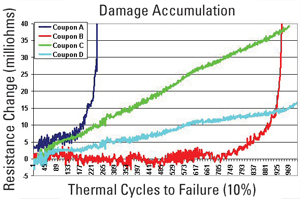
FIGURE 1. Resistance graph of failing and robust circuits.
|
Failure analysis preformed on coupons which have been subjected to tin-lead assembly and rework simulation of six thermal cycles to 230?C (6 x 230?C) predominately fail due to barrel cracks caused by metal fatigue. The cracks are frequently in the central region of the plated through-hole (PTH) and propagate between copper crystals traversing the barrel at an angle (Figure 2). With lead-free thermal excursion to simulate assembly and rework (6 x 260?C), the failure site tends to shift to knee or corner of the PTH (Figure 3), and the crack is similar to those seen with metal fatigue failures. Metal fatigue cracks at the knee or corner of the PTH can exhibit an accelerating failure rate while barrel cracks tend to fail gradually over time.
|
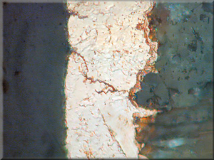
FIGURE 2. Barrel crack due to metal fatigue.
|
|
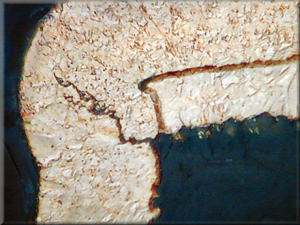
FIGURE 3. Corner crack due to metal fatigue.
|
In the thermal excursions required for lead-free assembly and rework, knee cracks and pad rotation are frequently associated with a ring of dielectric delamination around the surface pad, as shown in Figure 4. This condition is similar to the dielectric cratering that had been increasingly seen on larger ball grid arrays (BGAs). Knee cracks, pad rotation and the “lifted-pad” delamination are related to the high degree of z-axis expansion that occurs with the thermal excursions required for lead-free assembly and rework.
|
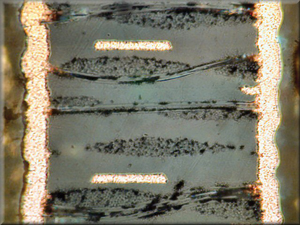
FIGURE 4. Pad rotation with delamination around the surface pad.
|
Thermal testing and failure analysis exhibit three general influences affecting PCB reliability. These influences can be ranked in order of dominance, where copper quality would be considered the primary influence, material quality the secondary and PCB design a tertiary influence. The influence of copper quality in the PTH includes copper thickness and distribution in the hole. It also includes the quality and robustness of primary metalization (electroless copper or direct plate) and the quality of the electrodeposited copper. Material quality includes whether the material is DICY cured or a phenolic system, the glass transition temperature (Tg), coefficient of thermal expansion (CTE) and other thermal characteristics. Design embraces the hole size, grid size and PCB lay-up. Fourth level influences less often play a significant role in reliability, and would include the presence or absence of non-functional pads, three-point contact, registration, drill quality, lamination, etc. It should be noted that any factor may become the dominant influence in a particular build, but in a well-made coupon the hierarchy present is relatively consistent.
In lead-free assembly and rework, the hierarchy of influence has a subtle shift where copper quality and material quality are competing to be the primary influence. Not only does the hierarchy of influence shift to increase material’s importance, but also the minimum acceptable quality levels of all influences are raised.
One of the most important lessons from the past year is that the copper quality, material robustness and design need to be in balance to produce reliable product in a lead-free application. In the tin-lead assembly environment one influence could compensate for a weakness in another influence. For example, a robust material could protect a coupon from failure if the copper plating thickness was on the low end of acceptable or exhibited a poor copper distribution in the PTH. Thicker copper plating could prevent early failures when lower quality materials were used. The word of the day for lead-free applications is balance. Today’s reality is that we need balance; a balance between copper, base material and design to assure reliability.
There has been a real shift in the effect of design and its role in reliability. Previously, if there was a conflict between an electrical requirement and a process limitation, the designer gave priority to the electrical requirement. With the complexity of PCBs today, and the added influence of lead-free processing, electrical parameters must be mediated against what is manufacturable, and what will survive lead-free assembly and rework. With small holes and grid sizes, the widespread use of microvias, sequential lamination, planarization of layers, buried, blind, capped and filled vias becoming more prevalent, there needs to be a better understanding of the reliability consequences of these structures after exposure to lead-free assembly and rework.
The biggest effect of thermal excursions associated with lead-free assembly and rework has been on material. The extra 30?C associated with lead-free assembly has brought materials to their limit. These temperatures significantly affect all but the most robust PCB materials. Delamination is becoming common. In reliability testing delamination of material will, in most cases, reduce the stress on the PTH. Reducing the stress in the interconnect structure extends thermal cycles to failure. If cycles to failure increase on the coupons that are exposed to the thermal excursion associated with lead-free assembly and rework, then it is likely the material is delaminated.
|
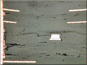
FIGURE 5. Crazing along glass fibers.
|
It appears from the data that some PCB materials are degrading with multiple thermal cycles to 260?C. Frequently we find one end of a micro section with material that appears mottled or spotted, followed by an area of crazing along glass bundles (Figure 5) and progressing to areas of frank delamination (Figure 6). Delamination may cross between B and C-stage layers or follow glass bundles. Small V-shaped delaminations may be visible at the hole wall or the ends of internal pads. In the worst cases material boils and oozes into the PTHs and appears as carbonized balls on the surface of coupons. Thermal cycle to failure data without a statement of material delamination or degradation can be misleading.
|
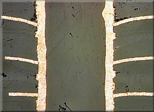
FIGURE 6. Cohesive delamination.
|
With the advent of lead-free assembly and rework the degree of Z-axis expansion can be severe. Robust materials tend to be elastic, returning to their original shape after thermal excursions. Material that is degrading starts to lose that elasticity and become plastic. Degrading material may undergo plastic deformation and remain deformed at ambient. The condition of plastic deformation produces an electrical hysteresis and shows up as damage acceleration in resistance graphs (Figure 1, coupons A and B). The effect is that with lead-free thermal excursions, the pads rotate (Figure 7) and remain that way, and cracks propagate and remain open at ambient temperatures. The z-axis expansion also puts greater stress on the electroless interconnection at outer layers. Interconnect type failures are more frequent and marginal metalization (electroless copper or direct metalization) may quickly fail.
|
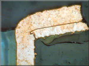
FIGURE 7. Pad rotation.
|
The effects of lead-free assembly and rework are reliability concerns. Using coupons that are tested as received as a baseline of performance, and comparing that data to coupons exposed to six tin-lead assembly and rework simulations (6 x 230?C), reduces the cycles to failure by 25% in an average construction. In a poorly fabricated PCB the cycles to failure may be reduced as much as 50%. Six thermal excursions to lead-free temperatures (6 x 260?C) typically reduce the thermal cycles to failure by 55% to 65% (Table 1 [PDF format]). The inference from this observation is that a poorly fabricated PCB, such as one that has a minimum plating thickness, poor copper distribution, and is fabricated with low grade material but subjected to tin-lead assembly and rework, can be more reliable than well-made PCBs that have been subjected to multiple lead-free assembly and rework cycles.
Even though lead-free assembly and rework may significantly reduce the mean time to failure, there has been little inclination to reduce the product lifetime expectations or to increase the minimum reliability requirements for compliance or acceptance testing. PCD&M
Paul Reid (This email address is being protected from spambots. You need JavaScript enabled to view it.) is program coordinator at PWB Interconnect Solutions Inc. in Ottawa, Ontario, Canada.


