As new prototype methods take hold, software must adapt as well.
3D printers have revolutionized the design of mechanical parts by using additive manufacturing methods to produce prototypes in a fraction of the time required by traditional subtractive manufacturing. Prototypes and production of printed circuit boards, on the other hand, continue to be produced by traditional subtractive manufacturing methods, often by manufacturers overseas that typically require two weeks’ lead time and charge prices that reflect the costs of preparing masks for and separately processing each layer of the board.
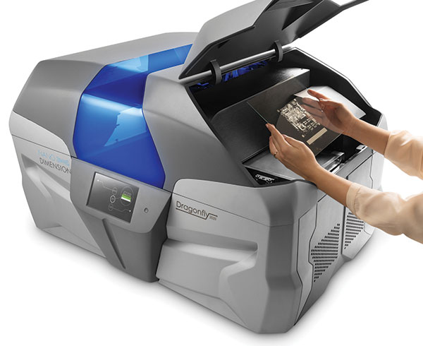
A paradigm shift is underway as a new generation of 3D printers makes it possible to produce PCB prototypes and low-to-medium-volume production boards in less time, at a lower cost and without intellectual property leaving the building (FIGURE 1). But the shift to 3D printing creates challenges for designers, including development of methods to design PCBs to a new set of design rules and seamlessly move data to the 3D printer while avoiding errors that could delay the product development process and waste expensive materials. These challenges are being overcome by a new generation of EDA solutions that support design for 3D printing by providing unique design rules to support the specific conductive materials used in 3D printing and optimization of the data to get the best result during the printing process. The next step should be integration of the design software with the printing software to eliminate the need for manual data input.

Figure 1. Nano Dimension’s DragonFly 2020 3D printer.
Limitations of Current Methods
Multilayer printed circuit board (PCB) manufacturing is today almost universally a subtractive process that involves working with basic materials, including copper foil and laminate cores. Copper foil is clad to both sides of a core consisting of woven glass epoxy-based material. A resist film is applied by heat and pressure to the copper foil surface. Gerber data are used to plot film that depicts the traces and pads of the board design. Ultraviolet (UV) light is shined through the clear areas of this film onto the resist, creating a negative image of the circuit. A chemical solution removes resist from areas that were not polymerized by the light. The copper is chemically removed from all areas of the core not covered by the resist, and the resist is removed as well, creating a copper pattern that matches the film pattern. Additional board layers are created, and these layers are bonded together under heat and pressure to form a panel with layers of copper on the inside as well as the outer surfaces. Various other steps are used to create vias and other features.
The manufacturing process described above is efficient when used to produce large numbers of boards. However, the entire process normally must be carried out from start to finish when producing even a single prototype board or small volume order, driving up costs and lead time. This represents a serious concern: prototypes are critical to the development of almost all electronic products because they permit physical boards to be tested under load to determine robustness, conductivity and signal integrity under actual operating conditions.
The traditional approach is to design the PCB and send the Gerber and drill files, or an intelligent format such as IPC-2581 or ODB++, to a local fabricator or a manufacturer located in Asia. The original equipment manufacturer (OEM) must contract with the prototype manufacturer, send the Gerber files, wait for the board to be produced, shipped, clear customs and finally be delivered for testing. Standard turnaround times are generally two weeks, although prototypes can be often produced in less time for a substantial rush charge. Costs on a per-board basis are high, and many prototype board manufacturers specify a minimum order quantity often far above the number of boards that are needed for testing.

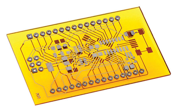
Figure 2. 3D-printed two-layer Arduino board printed on the DragonFly 2020 3D printer.
Sending valuable intellectual property to an overseas supplier is a major concern for many companies. Companies that make products with national security considerations have been limited to using an onshore manufacturer with the required level of security clearance, which may add considerably to both cost and delivery time of producing prototypes. Most designs don’t work perfectly the first time, so several iterations of prototypes are made. Additional iterations face the same cost and lead-time constraints as the first.
Going 3D
The introduction and proliferation of 3D printing of mechanical parts over the past decade or two has had a major impact on the manufacturing industry. 3D printing enables engineers to quickly and efficiently produce prototypes in quantities as small as one. 3D printers are affordable enough that many companies have purchased them, making it possible to produce prototypes in house. This dramatically reduces the time required for production of prototypes by eliminating the need for contracting with an external supplier, providing design information, waiting until the contractor’s schedule opens up and producing and delivering the boards. Bringing prototype production in-house also eliminates concerns that valuable intellectual property may leak out of the organization through a contractor. Most important, 3D printing enables the design team to build and test prototypes at a much faster pace than in the past. Increasing the pace of innovation often results in higher performing products.
3D printers capable of producing one-sided or even two-sided PCBs have been available for a couple years. But the vast majority of today’s electronics products use multilayer PCBs that are beyond the capabilities of these 3D printers. The challenges of creating a 3D printer capable of producing multilayer boards include the need to print both metal conductors and dielectric in the same build, while holding very high levels of accuracy in three dimensions.
The first 3D printers capable of producing multilayer PCBs to the standards required by electronics manufacturers have finally arrived, and others are expected to follow in short order. Major advancements that have finally enabled 3D printing of multilayer PCBs are specialty nanoparticle inks that print highly conductive traces and dielectric inks that provide the right amount of adhesion to work with a range of substrates.
If the market for 3D printers for PCBs follows the trend of the general 3D printing market and inkjet printing of electronics, the next few years will witness the introduction of a series of systems with increasing capabilities at a progressively lower cost. By reducing the cost and time required for prototyping, 3D printers are an effective replacement for outsourcing. Even greater potential benefit arises from making it possible for engineers to try out new ideas at a faster pace, which should make it possible to design higher performing, smaller, lighter, more stylish and less-expensive products. But the introduction of 3D printing presents the challenge of creating designs optimized for 3D printing. Materials used in 3D printing, especially the silver nanoparticle inks, have unique electrical properties and may require special attention.

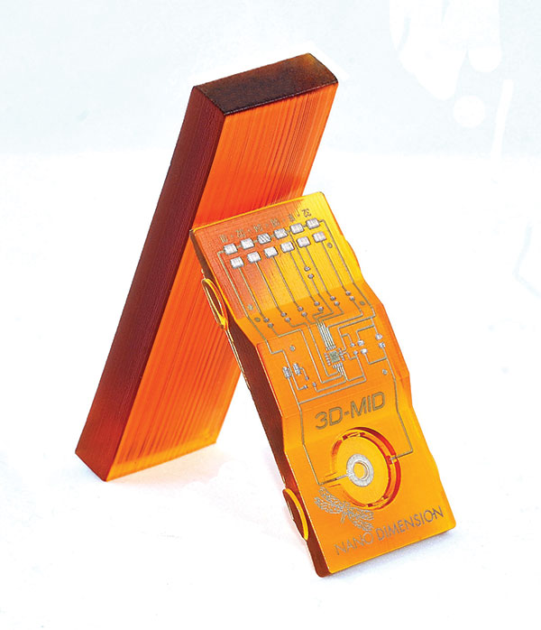
Figure 3. MID designs enabled by 3D printing.
Creating Design Data for 3D Printing
Perhaps the greatest challenge is accommodating the different materials used in 3D printing versus conventional PCB manufacturing. Preparing for 3D printing requires being able to support silver as a primary conductive material. Also, new materials must be easily accommodated to support future applications and technology. When it comes to printing technology, it’s important to ensure the ink droplets provide optimal coverage of each trace and pad. Most PC CAD tools are not designed for inkjet printing, so going from Gerber to bitmap or directly to bitmap may provide poor results. Post-processing may be necessary to ensure the bitmap file to the printer provides complete coverage. Another concern is that in conventional manufacturing the thickness of each layer is under control of the PCB fabricator, while in 3D printing, the thickness needs to be manually managed separately in the software used to control the 3D printer.
The challenge presented by designing for 3D printing bears a strong resemblance to the situation today in which many electronics OEMs use boards built by different contract manufacturers using different processes and different design rules. The challenge has been heightened over the past decade by the proliferation of manufacturing technologies such as flex circuits, low-temperature co-fired ceramics, etc., each with its unique design requirements. Each contract manufacturer has its own specifications for each of these technologies. As a result, OEMs must check their designs against an increasing number of design rule sets. The design must be compatible with all of these rule sets, or different versions of the design must be created to comply with these different rule sets. 3D printing of prototypes adds another unique and challenging design rule set.
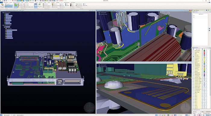
A potential solution to this problem is provided by a new generation of EDA tools supporting a native system-level 3D design environment and dedicated DfM software that supports the design and manufacturing of both traditional printed circuit boards and boards developed by 3D printing (FIGURE 4). Native 3D authoring software provides the ability to support a much broader range of technologies than current layout tools based on a 2D database with a 3D viewer.

Figure 4. The native 3D system-level environment of CR-8000 Design Force allows users to design and verify any technology, and fabricate or 3D print any board.
Design rule kits containing stack-up information, allowable material-dependent line width, spacing and vias can also be developed internally or developed as downloadable content online to ease the implementation of designs using 3D printers. The DfM software provides a platform to automate the process of applying the necessary rules for specific applications and ensuring the output is electrically and physically correct. This software incorporates a database of design rules from many different manufacturing processes. Design rules for processes and manufacturers that are not in the database can be entered directly. Users select rule decks to check the design against, modify rules as needed, browse violations, create documentation such as a spreadsheet with a list of violations and conduct signoff for 3D printing.
This approach provides a solution to the problem of creating a design ready for 3D printing and then turning around and readying the design for whatever subcontractor or internal production processes will be used to build the product. The designer can simply download a rule set for the specific 3D printer and material combination that will be used to prototype the design. The key differences in the design rules required by the copper foil and other materials used in traditional production processes versus the nanomaterials used in 3D printing are the line widths and spacing. It is important to validate the signal quality of high-speed signals since the properties of silver, the main conductive material used in 3D printing, differ from copper, the material nearly always used in production. Validating the PCB design against the special requirements of 3D printing makes it possible to produce prototypes quickly, while avoiding mistakes that consume expensive materials and delay the product development process.
Moving Data to a 3D Printer
The earliest 3D printers that attempted to print PCBs accepted design information in the form of STEP files, which are more suited to mechanical than electrical designs. The latest generation of 3D printers for PCBs now accepts design data as Gerber files with a graphical representation of each layer of the board, as well as an NC drill file. At the present time, additional design files used in production such as the netlist, bill of materials and placement information are not used in 3D printing. The operator of the 3D printer also has to define the thickness of each conductive and dielectric layer manually.
Since a single machine is used for 3D printing, producing PCB design data in a single file that contains the complete design definition would provide a major step forward. A strong candidate file format is the IPC-2581 standard, which is a single manufacturing file that contains all the intelligence of the design, including the stack-up information, placement and netlist. When 3D printers support assembly of the printed PCB, IPC-2581 will provide all the information needed for printing the part without further manual input. This approach promises to save considerable time and reduce risk of errors.
Conclusion
Prototyping PCBs plays a key role in the development process of most electronic products. 3D printing of PCBs can reduce the cost and turnaround time involved in producing these prototypes and can also provide a cost-effective alternative for lower-volume manufacturing. But some improvements are needed in the current design flow to take full advantage of the advancements enabled by 3D printing. A new automated approach to DfM efficiently manages the growing number of design rule checks needed to consistently produce good 3D printed PCBs. Consolidating all aspects of the design into a single data format, including layer descriptions and dimensions, can further simplify and error-proof the 3D printing process. These improvements will help with design and optimization of circuits for 3D printing, as well as the verification process.
Humair Mandavia is Chief Strategy Officer of the SOZO Center of Zuken, Inc. (zuken.com); This email address is being protected from spambots. You need JavaScript enabled to view it.. He is speaking at PCB West in September (pcbwest.com).


