Ensuring perfect alignment to avoid damage to traces.
Because their design withstands the demands of flexible circuits, zero insertion force (ZIF) connectors are a popular choice for attaching these circuits to other electronics.
A ZIF connector is similar to a card-edge connector for printed circuit boards (PCBs), but takes into account the specific connection needs of flexible circuits. The most common connector accepts a 0.3mm-thick circuit and is held in place by friction or a clamp-down strain relief. The principles of overlap ZIF design apply to circuits with typical 1.0 and 0.5mm pitches, as well as smaller, denser patterns.
Because the circuit is flexible, it can be damaged during insertion if care is not taken. By its nature, a ZIF connection requires the circuit be perfectly aligned for insertion. This is often tedious because of the small size of the connector and circuit. If the circuit is not aligned well and is forced into the connector, it can bend or fold in a way that may fracture the copper traces or connector pads. It is prudent then to pay close attention to the design of the flexible circuit and do everything possible to make it robust.
This is a four-step process that can guide any overlap ZIF design to ensure robustness. It starts with knowing the application.
Step 1: Understand the application. Before designing a ZIF connection, it’s critical to understand the application. Will the circuit route directly into the connector (FIGURE 1)? Will it make a slow, soft bend into the connector (FIGURE 2)? Or will it make a hard, sharp bend due to the lack of physical space (FIGURE 3)? These questions help designers identify any unique connection challenges that might occur or affect performance.
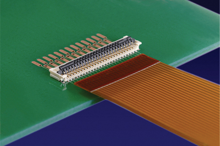
Figure 1. Molex SMT ZIF connector.
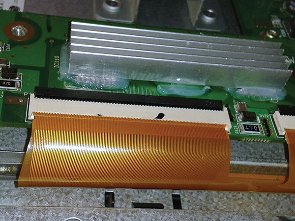
Figure 2. Soft bend ZIF.
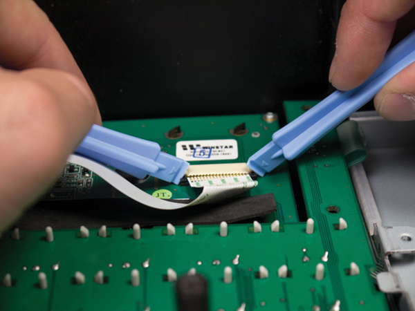
Figure 3. Sharp bend ZIF.
Step 2: Follow manufacturer specifications for connector pitch and width. Following the connector manufacturer’s specifications for pitch (space between pins) and width is a key part of ZIF design. Don’t compromise here, because pitch and width are the first things that will cause trouble in any ZIF design. These dimensions are crucial to alignment of the connector pins to their appropriate pad on the circuit. Any compromise in tolerance will permit the circuit to slide around in the connector, causing intermittent shorts or a cable that doesn’t fit into the connector at all. Be careful not to permit tolerances to stack up from one end of the circuit to the other when placing the pads at the correct pitch.
Step 3: Design to thickness specifications. Once the pitch and width are designed properly, the overall thickness is the next essential specification. The most common thickness specification for ZIF connectors is 0.3mm (0.0118"). This does not match a common thickness of flexible circuits, which is 0.006" to 0.010". To create the corresponding thickness, it’s typical to add a stiffener under the connector pattern. The stiffener material is not important. It can be polyimide, polyester or even FR-4.
In FIGURE 4, the thickness of the polyimide ZIF stiffener was omitted purposely. This permits the thickness to be adjusted to the construction of the circuit, whether it’s a single-sided circuit (as depicted), or a double-sided or multilayer circuit. The thickness requirement of ZIF connectors requires some calculation in order to meet the specification with the materials available. The thickness of the polyimide stiffener would need to be either 0.007" or 0.008" to meet the thickness requirement of 0.0118"+/-0.001". Another option, not shown in the image, is to adjust the adhesive thickness. No matter the method used to meet the specifications, the thickness must match the manufacturer’s specifications.
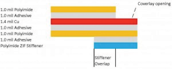
Figure 4. A polyimide ZIF connector with stiffener.
Step 4: Employ overlap for the most robust design. Once the specifications, width and thickness have been met within the required tolerance range, the final step in ZIF design is to make the connection as robust as possible. The orientation of the copper traces relative to the bend areas of the circuit are an important detail.
Robust design goes beyond simply lining up edges on top of each other. Instead, it uses a coverlay opening to expose the copper fingers for the ZIF connector and a stiffener to create the proper thickness. If the design lines up the stiffener edge with the coverlay edge with the trace to pad junction, there will almost certainly be fractures of the trace at the pad junction. The most robust design calls for the pad to overlap the coverlay opening, and the ZIF stiffener to overlap the pad/trace junction. This prevents the breaking of traces during circuit insertion. It also protects the circuit in dynamic applications or those times when a sharp bend is necessary to insert the flex into the connector (FIGURE 5).
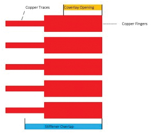
Figure 5. Overlapping the pad/trace junction protects traces during insertion or when a sharp bend is necessary.
With these four steps, designers can build a robust, durable ZIF connection for flexible circuits every time.
John Talbot is president of Tramonto Circuits (tramontocircuits.com); This email address is being protected from spambots. You need JavaScript enabled to view it..


