 Newer intelligent CAD output files reduce errors.
Manufacturing is all about taking data from the designer and delivering good working circuit boards. Well, it can be just data – as in full turnkey – or data plus some parts and or PCBs, as in a partial turnkey or a kitted job.
Regardless of whether parts and boards are sent, or if the EMS procures everything, your manufacturing partner needs good data, and a lot of it. That data are the difference between the working boards you want and need and a random jumble of expensive paperweights.
As an EMS, we need a bill of materials (BoM), the job specifications (which you give us by ordering and describing any special instructions on our website), and the CAD design files. Fab and assembly drawings are always a good idea, too. A little extra time spent on the files sent reduces risk, and that’s a very good thing.
The CAD design files include Gerbers, a centroid (that is, pick-and-place or XYRLS file), and intelligent CAD files such as ODB++ or IPC-2581. In some cases EMS providers can use the native CAD board file.
The ODB++ and IPC-2581 file formats are the future of electronics manufacturing. They come with more data, and more accurate data, than do Gerbers. If you can send either of these two, do so. Even if you have those, still send the Gerber files. Gerber is the lowest common denominator, and provides a base from which PCB fabricators and assemblers can work.
Gerbers are a set of files used to create the various layers of the board. Each layer requires an individual file, so a six-layer board (six copper layers) will typically require at least 13 distinct files: one for each copper layer, top solder mask, bottom solder mask, top silkscreen, bottom silkscreen, the drills holes, and solder paste for the top and bottom, if the board has SMT parts on both sides.
The drill file is combined with the Gerber files to line up the via and through-hole component holes with the appropriate spots in the PCB. Then the pick-and-place file will tell the assembler where to put each component, what angle to place it at, and which side of the board it goes in.
Fab drawings hold a human-readable description of the board, often in PDF format, and any special instructions the fabricator needs. The assembly drawing is the same, but for the assembler.
Sometimes the parts are too densely packed for the reference designators and polarity marks to show up on the actual board, or for aesthetic reasons, the designer doesn’t want them on the board. In such cases, all that information would be put into a set of assembly drawings: PDF files showing all the necessary reference information.
As of this writing, the ODB++ and IPC-2581 file formats aren’t universally accepted but are getting more so all the time. Use of these newer intelligent CAD output file formats helps reduce the number of manual steps and human interpretation, and will eventually lead to better quality and faster manufacturing times.
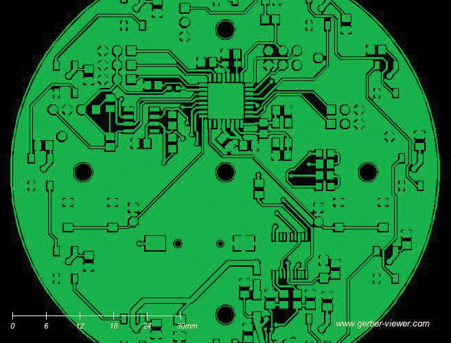
Figure 1. Sample Gerber file showing the top copper layer.
Duane Benson is marketing manager and chief technology champion at Screaming Circuits (screamingcircuits.com); This email address is being protected from spambots. You need JavaScript enabled to view it..


