Page 2 of 4
Inside IDX
The following sections offer a brief look at some of the main aspects of the EDMD data model and how it relates to the IDF:
Geometry. IDX supports the basic geometry of the IDF: polylines (connected sequences of line segments), circular arcs, circles, and composite curves (two or more polylines and arcs joined end to end). Parabolas, ellipses, b-splines, and other curve types are also permitted, although most ECAD systems do not currently support them. The points that define these geometric elements are confined to the x-y plane.
Lines and curves combine to form IDX curvesets. An upper and lower bound can be specified for each curveset, giving the curveset a “thickness” in the Z direction. This is how IDX gives thickness to the board, heights to components, and height-based restrictions on keep-ins and keep-outs. As with the IDF, IDX currently limits geometry to this 2.5D representation because ECAD systems do not generally support full 3D models. However, the EDMD data model supports a full 3D geometry representation for future use.
Shapes. Objects in a board design are created from IDX shape elements. Each shape element specifies a curveset and a type (for example, “part feature” for the board and component parts, and “non feature shape element” for keep-ins/keep-outs). A shape element can be “inverted” to create a void in another shape element. For example, a shape element can be inverted to create a cutout in the board shape.
Shape elements combine to create shapes for the board (called a “stratum” in IDX), assembly components, keep-ins/keep-outs, holes (called “interstratum features”), and other design objects such as mechanical parts. Because shape elements can be combined, it is possible to create board shapes with cutouts, and component shapes with more than one height.
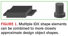
For example, the body of a DIP can be one shape element, and the rows of leads on either side can be additional shape elements. So, although geometry is limited to 2.5D in IDX, multiple shape elements can be used to closely approximate 3D shapes (Figure 1). In the IDF, components only have a single shape.
Items and instances. IDX defines the structure of a board design using items and item instances. Items represent the definitions of board design objects; item instances represent the occurrence of those objects in the board design.
An item can define a single object such as the board itself, a component, a hole, or a keep-out. Or, an item can define an assembly that includes other single objects or assemblies. Each item definition includes all the design information for an object, including its shape, identification and properties, if any. Items can be reused in the design. So for example, an item that defines a component part can be used multiple times in a board assembly.
An item instance is the occurrence of an item in the overall board design structure. Each item instance can include a transformation (currently limited to 2D) that determines the item’s location in the design. Assembly items can contain multiple item instances of single items or other assembly items. This permits IDX to represent hierarchical design structures.
For example, to support panelization as in IDF 3.0, an IDX assembly item could define a manufacturing panel that includes multiple instances of a board part (single item), or multiple instances of a complete board assembly (assembly item).
Roles. IDX extends the concept of ownership in IDF 3.0 with roles. Roles can be assigned to items and item instances to determine who has responsibility for those items and instances, and control who has the right to make changes to them.
Each role specifies a person or group, a type (owner or listener), a category (mechanical, electrical, organizational), a function (design, layout, thermal, etc.), and the item or item instance to which the role is assigned.
For example, with IDX roles, one mechanical designer can own connector locations, and another mechanical designer can own the board shape. The PCB layout group as a whole can own all other component locations.
Properties. In IDX, as with IDF 3.0, properties can be used to assign functional characteristics to component definitions such as capacitance, thermal resistance and power dissipation. Unlike IDF 3.0, IDX extends the use of properties to component instances, shapes, geometry, and most other elements of a design, including the design as a whole. The unit length property, for example, sets the global units for the design.
Properties in IDX can also be used to temporarily extend the functionality of the data model itself. For example, IDX 2.0 does not have an explicit way to represent the side of the board where a placement keep-out applies. Instead, this characteristic of a keep-out is represented as a user property on the keep-out item instance.


