 Drilling disparate materials can lead to an assortment of problems.
In our last installment, Mark Finstad talked about some of the things that can go wrong in the manufacturing process. Learning near the end of the process of a problem that will impact delivery can be frustrating.
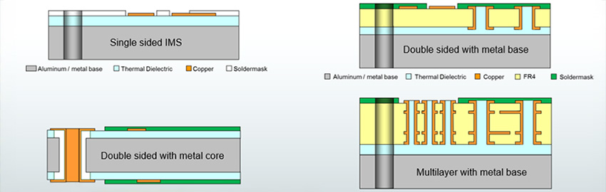
Once all the layers are laminated together, some risks still remain that need to be managed. For example …
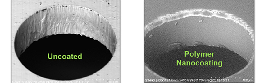
Poor hole quality. Rigid-flex constructions bring an extra challenge to the drilling process. Beyond alignment issues caused by differential dimensional stability, it can be more difficult to create a cleanly drilled hole. To make a reliable plated through-hole, the hole must be cut cleanly through the material and prepared properly prior to plating. Since the rigid-flex stackup blends a variety of materials, it is possible to have drilling flaws such as excessive nailheading of the copper, dielectric smear over copper surfaces in the hole wall, and material tear out. Consider the differences of drilling a sheet of steel versus drilling through plexiglass. Cutting steel creates clean metal chips, while cutting plexiglass often looks like the material was melted rather than drilled. Drilling rigid-flex involves cutting materials that are very different in terms of hardness. If not done properly, the result can be holes of such poor quality that plating will not be successful.
Leakers! This issue is unique to rigid-flex. In these designs, a portion of the circuit is flexible. These portions are protected with rigid laminate or other pouch material capped over the flex zone. This is done to keep wet process chemistry out of the flex layers and to avoid dragging entrapped chemistry from process to process. In some cases, a path is unintentionally created that allows chemistry to get inside the capped area. With heat and pressure of subsequent processes, this can cause staining. Also, some of the entrapped chemistry can leak back out during other processes such as etching, causing problems during that process as well. We call these leakers, and nobody likes a leaker!
There are other potential changes for failures along the process. The more complexity added to a part, such as multiple via structures, the more operations the part must go through and thus more opportunity for failures.
What does this all mean for the rigid-flex board, and how do we manage these risks? Established suppliers understand these risks and have controls in place to mitigate them.
Wet process equipment is supplemented with specialized rollers and transports to support thin flexible laminates. In some cases, leader boards or frames are used to directly support the material as it travels through the equipment. In some cases, the manufacturing panel may be laid out to increase the amount of copper on the panel to create support. This usually means fewer parts per panel and a higher unit cost. This is a balancing act for the manufacturer and may be one of the reasons the price is higher, or why the manufacturer may suggest a thicker dielectric to help manage costs.
To handle dimensional instability, a manufacturer does several things. First, it develops scale factors for every copper-clad laminate. This is based on copper and dielectric thickness, dielectric type, dielectric brand, as well as percentage of copper being etched away. Every material is different, so every material has a different scale factor. These scales are intended to match all layers together at the lamination stage. If a new material is introduced, an educated guess needs to be made based on experience. Often a scout run is employed to validate new scale factors. In the case of layers that have a high percentage of copper etched away, thieving may be employed to offset this. Thieving is the strategy of leaving nonfunctional copper in heavily etched areas to create stability. This has the extra benefit of helping make the panel stiffer, easing the process through wet processing and handling.
The manufacturer has drill strategies as well. Feed and speed tables are developed to optimize drilling through all different types of materials. These tables define how fast the drill bit spins, and how fast it is plunged into the panel. Optimizing this creates the best environment to cut material cleanly without either plowing through too fast and causing material distortion, or going too slow and causing smearing. Other strategies include selecting very specific drill bit designs with certain tip angles, flute shapes and cross-sections. The entry and backup materials that a panel is sandwiched between also have an impact, and the manufacturer will select specific materials based on the type of panel they drill. In some cases, the hole may be “peck drilled.” This is a process of drilling partially through the panel, then retracting the bit. This permits material to be cleared from the hole and provides time for the bit and hole to cool slightly.
While some consider copper plating black magic, a lot of science is involved. Manufacturers work very closely with chemistry suppliers to create a robust process that makes it possible to get copper to adhere to the variety of materials. It also requires strong process control to ensure every bath is optimized and well within specification. It is not uncommon for process engineering to monitor several hundred chemical components on a daily basis. One of the big advances in this area is automated feed-and-bleed systems that monitor baths and make small adds on a regular basis based on sensors and consumption. This has made a huge difference in plating bath control.
These are just a few of the control mechanisms to expect from manufacturers to ensure successful fabrication. Ask your manufacturer what attributes of your new design may expose you to higher-than-normal risks. They will be very glad to discuss which risk factors and options to reduce or eliminate. After all, no one wants to tell their customer parts failed during processing. A design for manufacturability (DfM) conversation with your manufacturer can reap huge benefits in terms of cost and meeting project schedules.
Nick Koop is senior field applications engineer at TTM Technologies (ttm.com), vice chairman of the IPC Flexible Circuits Committee and co-chair of the IPC-6013 Qualification and Performance Specification for Flexible Printed Boards Subcommittee; This email address is being protected from spambots. You need JavaScript enabled to view it.. He and co-“Flexpert” Mark Finstad (This email address is being protected from spambots. You need JavaScript enabled to view it.) welcome your suggestions.