Ultra-thin material plus dimensional instability: What could possibly go wrong?
Question: I have been buying rigid and flex PCBs for many years from multiple suppliers and have found lead times for flex PCBs often seem much longer than those for rigid PCBs. Even with the longer lead times, many more promised ship dates are missed by flex PCB suppliers than rigid PCB suppliers. Why is this?
Answer: The reason for the extended lead times could be due to the type of flex you are buying (e.g., rigid-flex). Rigid-flex construction has a lot of extra processing steps that naturally add to lead time compared to a similar rigid board. As far as missed lead times, this is usually the result of something going wrong during processing. Flex and rigid PCBs share many potential processing pitfalls, but beyond those issues, flex has several additional attributes that could be potentially troublesome. Virtually all these issues are caused by the ultra-thin materials used in the construction of a flex or rigid-flex circuit. Following are just a few things (there are lots more) that could cause the fabrication to “crash and burn” for your flex circuit supplier.
The “log jam.” Materials used for flex and rigid-flex construction are thin. Really thin. It is not uncommon to have copper-clad laminates 0.002" to 0.003" in total thickness. These extremely thin laminates are very fragile and prone to dings, dents and wrinkles. Even when you do everything right, the result is sometimes disappointing.
Look, for example, at the developing, etching, and resist stripping processes. If rigid PCB panels are run through these machines, the panels can be laid right on the conveyer wheels. The panels will track through the equipment and seldom encounter any issues.
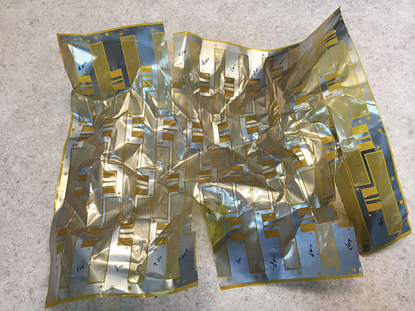
Flex material is way too thin to run through these machines unsupported, so the flex panels are typically attached to a rigid leader board to help pull them through. Occasionally, the flex panel will cause enough drag on the leader board that it slows down and can be overtaken by the next panel coming through the machine. See where this is going? By the time the operator realizes nothing is coming out the other end of the machine, there is a horrendous mess of crumpled panels covered with whatever chemical they were being doused with. It is rare any material that was part of this log jam is salvageable (FIGURE 1).

Figure 1. When panels get hung up in processing equipment, they are rarely salvageable.
Stretch and shrink. In addition to being very fragile, thin laminates are also prone to dimensional instability. Copper-clad flex laminates tend to shrink when copper is etched away, and they tend to stretch during mechanical scrubbing operations. The stretch/shrink is often not the uniform over the x and y axes. Also, polyimide base material can stretch and shrink due to changes in temperature and humidity, and, again, it is often not uniform over the x and y axes. Now imagine lining up 0.012" or smaller pads on multiple layers when each substrate is doing its own thing. LDI (laser direct imaging) printing and HDI processing has helped a lot by permitting the equipment to compensate for material movement. But considering the cost of an LDI, most fabricators don’t have more than a couple of these machines, so they have to be selective about which jobs run through them. Many circuits are processed without the fancy equipment; in those cases, stretch and shrink can be a real problem. Additionally, the larger the circuit, the more problematic dimensional instability becomes.
Copper plating. Flexible circuits are bonded together with thermosetting epoxy or thermosetting acrylic film adhesives. These adhesives have great bond strength and dielectric properties, but are not so great for thermal properties. When exposed to elevated temperatures, these films tend to expand considerably in the z axis. This expansion can wreak havoc on the barrels of plated through-holes, causing cracks in the plated copper. While this phenomenon rarely causes problems on low-layer-count flex circuits, it can be a real issue on boards of six or more layers. Second, when a through-hole is mechanically drilled in a rigid PCB, the drill bit causes micro-shattering of the glass fibers in the laminate, which makes the hole wall rough and porous. Copper plating solution is able to penetrate the porous surface of the hole wall and bond very well. With flex however, all the materials are non-reinforced films, so the resulting hole wall from a mechanically drilled hole is very smooth and non-porous. As you would expect, plated copper does not bond as well to a through-hole in a flex circuit as it does to one in a rigid circuit. Occasionally, microsectioning will reveal copper separating from the hole wall, which dooms every part on that panel to the scrap barrel.
This is part 1 of 2. Nick Koop will continue in his next column.
Mark Finstad is senior application engineer at Flexible Circuit Technologies (flexiblecircuit.com); This email address is being protected from spambots. You need JavaScript enabled to view it.. He and co-“Flexpert” Nick Koop (This email address is being protected from spambots. You need JavaScript enabled to view it.) welcome your suggestions. They are speaking next month at PCB West (pcbwest.com).


