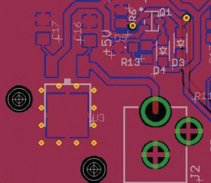
Rethinking the design can lead to fewer passives and a smaller board.
AT THE MOMENT, I’m working on an Arduinocompatible clock. Like most of my Arduino-compatible boards, this one uses an Atmega32U4, with USB built in. With the Atmega32U4, I sacrifice a little in program memory and SRAM, but gain a bit in reduced parts count.
A USB-capable Arduino-compatible is, of course, programmed via USB, and can be powered by the USB port. Most Arduino boards also have a 5V regulator to be used when being powered by a wall-bug power supply. Naturally, I put the USB connector on the clock board, as well as the 5V regulator. With the two different supplies, I also put in circuitry to auto switch sources and protect the USB host when both supplies are connected at the same time.
My first PCB revision required a few hand modifications, but not many. Still, I decided to re-spin the board and remove the two mod wires. While doing so, it suddenly occurred to me – a blinding flash of the obvious – that most cellphones and other small devices are charged with a USB-connector 5V wall-bug power supply. Why, then, would I also need a separate power supply and on-board 5V regulator?
By pulling the regulator off of the board, I could eliminate a few capacitors and the supply auto-select/protection circuitry. Not only did I save in component cost, but I was able to reduce the PCB size, and thus cost, by about a third.
- Originally, I had the 5V regulator in the design because “Arduinos can be powered by either USB or a non-regulated power supply.”
- The reverse power protection is necessary to prevent damage to the USB host if the other power is also connected.
- The auto-power switching circuit is necessary so that a user doesn’t need to flip a switch or change a jumper when changing power sources.
- I had two extra LEDs to indicate which supply was powering the clock.
That’s 11 components, in total, that I removed by asking myself, “Why am I doing it this way?”
While in this case I was working on a DIY project, the thought process can be applied to any circuit board design. I questioned my original assumptions, found a “because it’s always done that way” and eliminated it. Assumptions are meant to be challenged.

FIGURE 1. Eliminating the redundant on-board regulator saved space and cost.
Ed.: Read Duane’s blog at circuitsassembly.com/blog/.
DUANE BENSON is marketing manager at Screaming Circuits (screamingcircuits.com); This email address is being protected from spambots. You need JavaScript enabled to view it.. His column appears bimonthly.


