
The right data package will speed assembly and test programming.
The tendency in engineering to find the big or obvious ways to increase margins can overlook the subtle but potentially significant ways to increase profitability. One of the most subtle ways to decrease production cost while getting to market faster is to reexamine the type of data provided to your EMS partner.
As you dig into which data format is best and why, understanding the types of data is important. The first and highest level of data is the binary database. This database is the core of the CAD system. It’s not an output, but rather the file format that is saved throughout the design process. Most EMS companies will find this database useless unless they have a more advanced services offering, including design layout through manufacturing. All outputs discussed past this point are derived from this file format.
The most basic form of data is Gerber data. Gerber has been the standard for PCB bare board and stencil manufacturers; it’s an output known by all. A little over a decade ago EMS companies began to move away from centroid data to this more standard output. Whether this was the choice of the EMS or brought about by customer pressure is unclear, but it did become a common data format for EMS companies to program their lines.
Gerber was not a good choice for EMS companies then, and now is outdated for bare board and assembly companies for many reasons. Gerber data are unintelligent bulky data, providing nothing more than a picture of what the board should look like. There is no centroid/x,y information for placement, no component or connectivity intelligence. For EMS companies, programming takes significantly longer and is error-prone, forcing more debug on the pick-and-place line.
FIGURE 1 shows the process of outlining a part, one of the steps in programming a board using Gerber in the pick-and-place process. Parts are laid out in a symmetrical pattern with no silkscreen, making it difficult to know which pads should be paired. It is not uncommon for the BoM provided by the OEM’s engineering group to differ from the one provided by the OEM’s procurement department. The Gerber data approach does not give the EMS company the ability to have a set of checks and balances to verify a match between the BoM and build data.
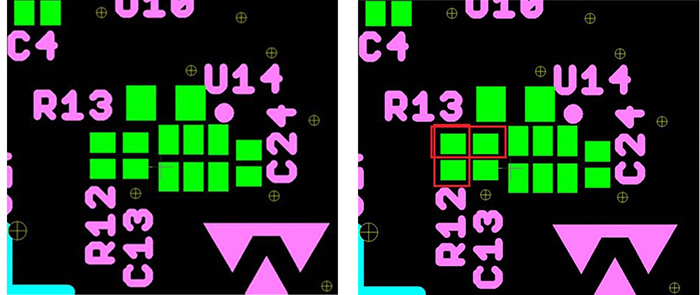
Figure 1. Without the silkscreen, it is difficult to know which pads should be paired.
Programming and line prep is no different from any other process; errors caught earlier in the process are less costly than those caught later in the process.
Imagine holding up a million-dollar line for hours over a simple mismatch between the BoM and the data provided. While historically Gerber has been the default for board and stencil vendors, the trend even with them has been to move away from this data format to the intelligent data process.
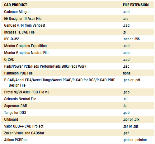
The intelligent data file comes in many formats, the most common of which is Valor ODB++. At its core, the intelligent data file is an ASCII database that every CAD system has the ability to output. There are many benefits to the use of the ASCII database, the first of which is a single file approach and its smaller file format. While that is a nice feature, the speed at which the pick-and-place machines can be programmed with the ability to have BoM checks and balances is where the significant difference can be seen. At a minimum, the programming can be two-to-three times faster, saving hours of programming while significantly lowering the risk of mis-programming the lines. Then these same data can be used to program the test and AOI equipment, and to create the drawings used throughout the entire build process. It’s important to keep in mind there is a difference in ODB++ and ASCII CAD data. Valor ODB++ generally takes a little longer for the EMS facility to use in programming, so often a EMS company will prefer ASCII (TABLE 1). These data are accepted by most flying probe testers, AOI and supports, creating drawings for the entire build process.
Are you ready to dump Gerber for the super-smart ASCII database? Hold on, not so fast. There is more to the equation.
The data package submitted to the EMS company should not be just one file. In fact, the process for preparing data should be seen as more than handing inputs to a service provider. FIGURE 2 shows all the inputs required for the four major phases of the development and production of your electronic system, specifically for circuit boards. As far as data go, it’s important to provide all the information your EMS provider may need. Although EMS providers vary in ability, sophistication, and offered services, the data package can be a “one size fits all.” Here is the “what and why” of the recommended data package:
- Gerber data, which board and stencil manufacturers still depend on for their processes. There will be a point when this is not required. Depending on your vendor base, that time may or may not be now.
- Valor ODB++, which allows board and stencil manufacturers to gain insight into the design and offer feedback to improve processes, thus reducing production cost over time. It also allows use of Valor DFA software for reviewing an assembly to improve yields in production by PCB manufacturers with that level of sophistication. Since it can be used for programming pick-and-place lines, it could be a “one file” approach to all manufacturing requirements.
- CAD ACSII database, which supports the fastest approach to programming the pick-and-place lines and can support other programming efforts such as AOI.
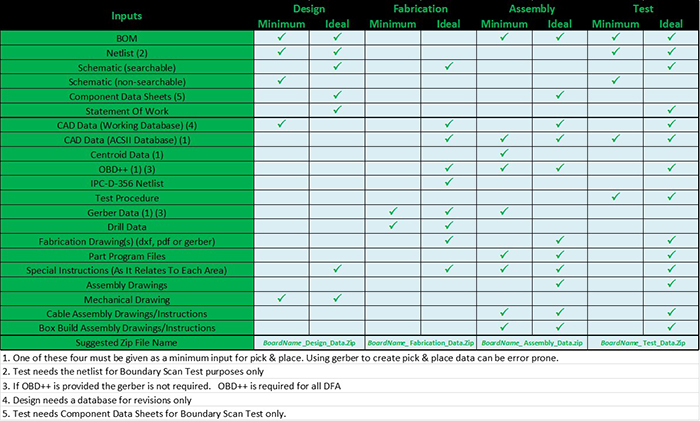
Figure 2. Required and preferred files for design, fabrication, assembly and test.
The above data package is complete, and will allow any EMS company to support your build requirements. If you want a “belts and suspenders” approach, or are using an EMS provider with PCB design layout services, include the binary CAD database. This gives them the ability to dig even deeper into the data to supply the best feedback and support.
The old school approach of using unintelligent data for build process is more expensive in the long run. It will be subtle, and some may never understand the cost borne by not modernizing the data package for their vendors. Intelligent data drives speed, quality, and allows reviews of the design, flushing out long-term manufacturability issues early in the process. This is all possible without spending any money on software, because all the data recommended are natural outputs from the CAD system.
Table 1. Common CAD Files and Their Extensions
W. Scott Fillebrown is chief technology officer of Libra Industries (libraind.com); This email address is being protected from spambots. You need JavaScript enabled to view it..


