When thermal mismatches are to blame, what’s the cure?
One root cause of bridging with TSOP components is a size mismatch between the TSOP (U2, 24-lead) and the SMT pads. Typically two problems are caused at reflow due to component-footprint mismatch: bridging and insufficient solder volume. Bridging is the result of a thermal mass mismatch between the pad and component lead, and most often occurs with gullwing devices. The foot (toe-to-heel) has a much smaller thermal mass than the pad and heats more quickly in the reflow oven. Molten solder will wet more aggressively to a hotter surface, so the majority of the solder volume pools at the toe and heel and does not evenly coat the pad and component lead. The gullwing lead cannot wet all of the excessive solder volume, and the excess flows off the SMT pad, bridging to the adjacent pad.
Insufficient solder volume is a result of too much surface area for the solder to wet to, and most often occurs with QFNs and RNETs. Since the surface area differences are not nearly as drastic as those with bridging, the temperatures of the SMT pad and the component terminations are much closer during reflow. As a result, solder evenly wets to both surfaces. However, a pad that is too large requires extra solder volume to evenly wet all surfaces and still create a Class III solder joint. Component shortages and substitutions, and poorly designed boards, can cause either, or both, of these problems.
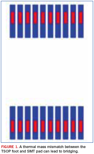
For this board (Figure 1), the bridging with TSOP U2 is the result of a very small foot (red) and a very large SMT pad (blue). The foot length is 0.0246" and the SMT pad length is 0.069". The foot only covers 36% of the pad length. For a properly designed board, the foot should cover approximately 75% of the pad length. The foot is getting much hotter than the pad during reflow, and too much solder volume is pooling at the toe and heel. Solder is flowing off the pad, causing bridging.

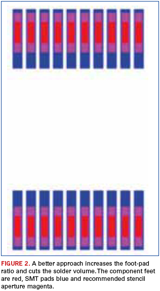
To eliminate bridging, the printed solder volume must be substantially reduced, given the very small component feet and the very large SMT pads. The recommended stencil aperture size is U2: 0.009" x 0.0485" (36% volume reduction).

Robert Dervaes is vice president of technology at FCT Assembly (fctassembly.com) This email address is being protected from spambots. You need JavaScript enabled to view it.. His column runs monthly.


