As a result of increasingly complex mechatronic components, the significance of an interdisciplinary engineering approach is more apparent than ever.
The management of data generated by different development tools, as part of a holistic product development strategy, is particularly necessary and can be helped by a connection to an existing product lifecycle management (PLM) system, allowing not only for a process-safe exchange of product data, but also improved cooperation in the development of interdisciplinary projects.
During development of products with both electronic and mechanical components, greater levels of coordination are required, partly due to the traditional use of drawings, draft circuit diagrams or circuit board layouts, which are greatly influenced by the requirements of each discipline, instead of facilitating a cooperative approach. This way of working leads inevitably to longer projects and higher expenditure. The challenges faced today can be attributed to the following three factors:
1. Differing development tools. In the past, it was possible to create circuit diagrams and 2D drawings with the same CAD programs. Now, in recognition of the increased requirements for quality and functionality in design and the increased complexity of the components produced, CAD programs have been developed to the specific requirements of the different engineering disciplines, leading to a separation between the tools used by mechanical and electrical engineers. Whereas in mechanical development, 3D CAD systems are the tool of choice, in electrical/electronic (E/E)1 development 2D design tools are more widely used.
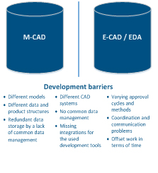
Figure 1. Development barriers affecting E/E MCAD collaboration.
2. Differing basis for cooperation. When asked to describe their projects, mechanical and electrical engineers are shown to respond very differently, making the cooperation between the different CAD and Development systems even more challenging.2 While mechanical engineers present their work with technical drawings, EEs prefer using a circuit diagram. It becomes increasingly clear, with further investigation, that in the various disciplines, different thinking patterns and models dominate, which can only be interpreted by other engineers within that field.
Mechanical engineers work primarily with assemblies and focus more on the structure of the construction itself and the construction steps contained within it. An electrical component would be viewed as just one building block in a structure of many that need to be integrated together. On the other hand, EEs prefer to organize components by function, into function modules based on divisions perceived as logical in electronic engineering.
3. Barriers to collaboration. The ways in which engineers can work together are strongly influenced by which of the aforementioned development tools are used. At the moment, there is a too stronger emphasis on the individual engineering disciplines when developing products with both mechanical and electrical parts. Although communication between engineers in different departments to some extent takes place, it is often constrained by different ways of thinking and insufficient opportunity for interaction.
A lack of integration solutions in electrical and electronic engineering also plays an important role here. Available interfaces are often prone to failure or lack the necessary process support. Furthermore, the collaborative management of generated data and its standardized connection in a supporting PLM system is rather the exception, than the rule.
The product structure of mechanical and electronic components are also very different, making the joint management and storage of the generated data and therefore collaboration even more problematic.
Collaborative ECAD/MCAD Development
The aforementioned barriers to collaboration often lead to "isolated solutions" and poor data management, preventing the successful combined development of mechanical and E/E components in a joint assembly – that is a requirement of many modern engineering projects today.
However, it is possible to overcome these problems by successfully linking the different development tools and by using a PLM system for the joint management of data and depiction of shared product structures.
For example, without an integration solution between ECAD and PLM systems, all bill of materials (BoM) data must be inputted manually; whereby an ECAD PLM system integration allows joint use of assemblies and BoM structures, automating multi-disciplinary BoM creation. Redundant data, which can impair the product development process, creating unnecessary development work, is also avoided. The technical and organizational benefits of successful CAD and PLM system integration can be seen in FIGURE 2.
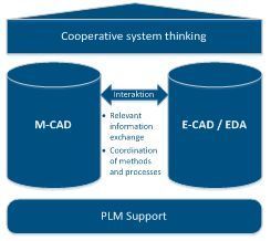
Figure 2. Improved E/E MCAD collaboration via PLM integration.
The Solution in Practice
The gaps between mechanical and electronic development can be closed in practice through the joint management of data and integration of development tools. Therefore, the structure of components developed in ECAD development tools can be imported from the relevant application in to the mechanical construction program. The design engineer can then continue to develop the mechanical model without needing to construct a separate version. Changes to the mechanical structure can then be re-imported easily in to the E/E development tool.
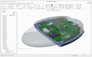
Figure 3. Collision check – Board imported from Altium Designer in to Creo Direct Modeler.
This process also works in the other direction. For example, mechanical components, such as housing, can be imported in to the ECAD tool and depicted visually, so that the electronic designer can take the mechanical structure into account and prevent conflicts between the two.
The jointly developed product structure is then saved in the PLM system as a combined BoM, making both mechanical and electronic model data equally available. In addition, the automated comparison of the ECAD component library with the PLM system drastically reduces the need for excessive maintenance, thus improving the collaboration between development engineers across different departments.
Benefits
The creation of a joint product structure makes it possible to manage all product data in one system, ensuring greater process security and traceability for product liability in comparison with manual processes. Automated functions such as versioning, storage, naming and BoM synchronization relieve the designer of manual data maintenance tasks, while reducing mistakes and redundant data storage. Component libraries can also be managed directly in the PLM system, and the necessary design templates loaded in the ECAD or MCAD systems. Furthermore, defined configuration, release and modification processes offer further advantages to the product development process. All actual information is available in the PLM system and can be easily forwarded to relevant business units, such as sales, purchasing and service, making project communication easier.
References
1. In the industry the terms ECAD and EDA are used inconsistently to describe electrical and electronic systems. This article will therefore use the term electronic development to refer to both to Electronic Computer Aided Design (ECAD) and the Electronic Design Automation (EDA).
2.Fraunhofer IPT, et al, "Systems Engineering in the Industrial Practice, ["Systems Engineering in Der Industriellen Praxis"].
Marc Hutsch is global sales manager, XPLM Solution (xplm.com); This email address is being protected from spambots. You need JavaScript enabled to view it.


