
Dual-row versions offer superior density, but at what cost?
This question was posed to me a few months ago on a visit to a prospective customer. The prospective customer showed me the picture in FIGURE 1 and stated all three of his current flex circuit fabricators had built parts with this zero insertion force (ZIF) contact pattern. All the parts seemed fine at receiving, but after installation ~5% developed cracks in the areas circled in red. His question: Was this a manufacturing issue or a design issue?
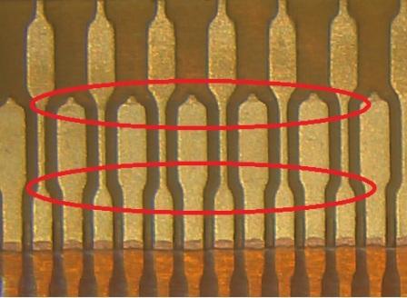
Figure 1. A zero insertion force (ZIF) contact connector like this was showing cracks in the circled areas.
Considering the issue was spread across three different vendors, and one of my existing customers had reported a similar issue just a week earlier, I was fairly confident it was not a supplier issue. This particular ZIF connector style has some distinct differences from older, established ZIF connectors (FIGURE 2). Considering the older style has been around for decades and has been a very reliable connection option, I figured one of these differences was causing the newer style to be more prone to problems.
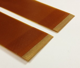
FIGURE 2. Older ZIF connectors have a single row of terminations, while the new dual-row style can handle more traces.
Feature size. Both styles typically have NiAu-plated contacts on the flex. The reason for using this connector over the older style is connection density. The older style with straight inline fingers is limited to one row of terminations. The newer version has two rows of terminations, which effectively doubles the number of traces run to that connector. To do this, the traces feeding the outermost row of pads must snake between the inside row of pads. These conductors have a nominal width of 0.1mm, which is considerably smaller than anything on the single row ZIF. The recommended flex PCB footprint also shows a very sharp neck-down to the 0.1mm width. Coincidentally, that is where the cracks always show up. Smoking gun? Maybe, but why then would the traces crack when they are securely clamped in the ZIF connector?
Overall thickness. The newer style requires 0.2mm overall flex thickness in the ZIF area, as opposed to 0.3mm overall thickness requirement on the single row ZIF. That is a pretty big difference in terms of both percentage, as well as the resulting loss of stiffness. But again, why would a thinner flex develop cracks when it is securely clamped in the connector? Answer: it doesn’t.
Since one of our customers was struggling with this issue, we put a significant amount of time and resources into finding an assignable cause. We made hundreds of test parts that our engineers carefully installed and tested. We varied trace width and ENIG thickness. We even made samples with a modified PCB footprint that gently tapered the wider conductors to the 0.1mm width.
After hundreds of tests, we could not recreate the problem. Then the test engineer got careless inserting a flex into the ZIF connector. He did not have the flex circuit lined up correctly, and when he applied pressure to insert the flex, it went in partially and then bent sharply like an accordion (due in no small part to the 0.2mm thickness and resulting flexibility). He was planning to realign and reinsert the flex, but decided first to do a quick inspection of the flex contacts. And there they were. Many of the 0.1mm traces had cracks all or part way through them right at the neck-down area.
We then took all the parts we had made for testing and built some controlled-bending fixtures to see how much one of these parts could be flexed in the contact area before cracks started to form. As it turns out, not much. Most test circuits could tolerate a one-time bend of 45° with no more than some visual stress lines showing on the gold surface. But that is where the good news ends.
One-time bends of 90° or more caused cracks in virtually every one of the ENIG-plated test circuits, even though high-ductility nickel was used under the gold. Even a good number of the test circuits with just bare rolled annealed (RA) copper (no final finish) showed cracks. The scary thing is a lot of the cracks were only partially through the conductor, so they still had continuity. But if the assembly is subjected to any shock or vibration, those cracks will propagate and cause opens at a later time.
I brought this issue up at the IPC-2223 meeting at IPC Apex Expo in February. Many manufacturers and users shared similar problems with this connector type. In a nutshell, if the required connectivity can be attained using a single-row ZIF connector, that is what I would recommend. If the required connection density drives use of the dual-row version, it is imperative assembly operators understand how fragile this connection type can be, and if the flex is inadvertently flexed in the contact area during assembly, it must be removed and thoroughly inspected prior to completing the installation.
Mark Finstad is senior application engineer at Flexible Circuit Technologies (flexiblecircuit.com); This email address is being protected from spambots. You need JavaScript enabled to view it.. He and co-“Flexpert” Nick Koop (This email address is being protected from spambots. You need JavaScript enabled to view it.) welcome your suggestions.


