Microsectioning of Laminates
Lab studies show variances in hardness and fragility mean procedures need to be tailored to a specific resin system.
Microsectioning can be an extremely useful technique to inspect PCBs. However, incorrectly prepared samples can lead to wrong interpretation of the results.1 Determining the right parameters for microsectioning involves a combination of experience and understanding of how different sample preparation parameters can affect the final results. Furthermore, fiber-reinforced composites tend to be difficult to cross-section due to the large difference in mechanical properties between the matrix and fiber.1
Therefore, the microsectioning process needs to be tailored for the components of the laminate or printed circuit boards. Microsectioning steps include sectioning, mounting, grinding and polishing. A description of each step will be described in this article.
Sectioning. For manual and semiautomatic sample preparation, abrasive cutting is a common sectioning method. The selected method of sectioning needs to create minimal damage to the sample.1 Use of serrated blades must be avoided, as it can significantly damage the samples.2 If an abrasive band saw or cutting wheel is used, the use of abundant amounts of lubricant (water or as needed) is recommended to avoid local overheating. Frictional heating can induce damage on the sample, especially on the edges.1,2
Some of the defects created during sectioning are cracks, microcracks and induced matrix strains.2 As seen in FIGURE 1a, excessive fiber pullout and cracking at the edges of the coupon can be generated by using inadequate sectioning methods. In this particular case, the coupons were cut using a dry diamond saw and excessive pressure during cutting. A similar coupon was cut using a router, and no significant section-related defects were observed (FIGURE 1b).

Figure 1. Details of defects generated from inadequate sectioning: (a, left) excessive fiber pull-out and (b, right) crack at the edge of the sample. Samples were cut using a dry diamond saw and mounted in acrylic. The samples were ground and polished using SiC papers: 180, 320, 500 and 1200 grit; 9 and 6µm diamond and 1µm alumina.
Another common technique for sectioning involves use of a router. A router is a micro-milling device that uses diamond tools to create high-quality surfaces. This machining process is fast and has good edge retention1 (FIGURE 2). Use of a router or diamond wheels will minimize damage created during sectioning, eliminating the need to use very coarse grinding papers (<180 grit) after cutting.

Figure 2. Details of surface finishing after sectioning coupon using router. The sample was prepared using the same procedure as in Figure 1b.
Mounting. In most cases, laminates and coupons are mounted in casting resins. Mounting helps support the sample, create a flat surface, and prevent additional damage during grinding. An ideal casting material should fully impregnate the samples and help preserve preexisting defects for further inspection.2
Some general requirements for the selection of a good mounting material and method should include3:
- The mounting procedure should not physically or chemically damage the sample.
- The mounting material should provide good edge retention and be able to penetrate pores and crevices.
- The mounting material and the sample should have similar abrasion rates.
- Good chemical resistance to solvents and etchants should be used during the sample preparation process.
The mounting material and technique should not damage the sample. In the case of fiber-reinforced materials, cold mounting (castable resins) is preferred over a powdered compression resin (e.g., Bakelite)4, as no pressure is applied during casting.3 The most common castable resins are acrylics, polyesters and epoxies. Acrylics cure relatively fast but do not provide good edge retention. The main advantage of acrylics is the rapid cure time (fewer than 30 min.), which can expedite the sample preparation process. Nonetheless, acrylics can generate significant amounts of heat during the curing process.1 The peak temperature reached during curing will depend on the volume of the mix, environmental conditions, and the design and material of the mold. For instance, Nelson reported peak values of 132°C for samples mounted in acrylic using a glass mold (bad heat conductor) versus peak values of 42°C for aluminum molds.1
In the case of laminates and printed circuit boards, the most common mounting media is epoxy and acrylic. To determine the peak temperature reached during curing, we conducted an experiment in our lab. Three identical pieces of 60-mil unetched laminates were mounted in silicon molds. A thermocouple was placed next to each sample, and the temperature at the surface of the laminate was recorded during the curing cycle. Results are shown in FIGURE 3. The results indicate that, as expected, the samples mounted in acrylic see higher temperatures than the samples mounted in acrylic.
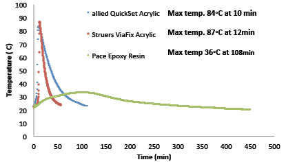
Figure 3. Temperature versus time curves for laminates mounted in acrylic and epoxy.
Additionally, the criteria for selecting mounting media should account for hardness compatibility within the sample and the resin.2 Large differences between the hardness of the sample and the mount resin can lead to inhomogeneous grinding and polishing, causing poor edge retention.2
Epoxy resins have higher hardness and low shrinkage, providing excellent edge retention of the mounted samples.2 Moreover, Rockwell M hardness measurements carried out in our lab indicated significant differences on the hardness values for the acrylic mounts (33-40 Rockwell M) and the epoxy mounts (77 Rockwell M). The epoxy mounts have values closer to our resin systems and will provide a better edge retention during grinding and polishing. The main disadvantage of the epoxy castings is that the curing time can take up to 12 hr. at room temperature for some systems.2 However, the curing time can be reduced by heating the ensemble to slightly elevated temperatures (50 to 75°C).3
Grinding. Grinding involves the removal of material from a preexisting surface to create a new surface. The new surface is generated by the creation of new scratches that are finer than the preexisting scratches in the sample. This process requires multiple steps and should produce a flat surface. The main goal of a good grinding process is to minimize the depth of the damage and maximize the material removal (abrasion rate).3
After the samples are cut and mounted, grinding and polishing are required for inspection of the samples under the optical microscope. During grinding, the sample is ground using a sequence of abrasive papers. The starting paper grit size will depend on the magnitude of damage created during sectioning1 and the amount of material that needs to be removed in order to reach the target area for inspection.
The initial grinding is used to remove the damage from sectioning1 and get close to the target holes or selected area for inspection. The damage created by coarse grinding must be removed during the subsequent grinding step. If damage created during the initial grinding is too severe, the subsequent polishing steps will not be sufficient to efficiently remove the damage.1 The result of each grinding step should be a surface with uniformly distributed scratches, with no evident residual scratches from the previous step.
Abrasive grinding creates two types of scratches: The first type is responsible for material removal and occurs when the surface of the sample is in contact with abrasive particles with favorable cutting angles (close to 90°); the second type of scratches does not favor material removal and is responsible for surface deformation.1
Grinding should always be done using lubrication. In general, the lubricant (usually water) used during wet grinding can minimize heat-generated damage and residue entrapment on the abrasive paper. Use of a lubricant helps separate the material that has been removed and expose the abrasive particles to the sample.1
Several parameters can be controlled during grinding, including applied load, speed of the wheel and grinding paper (type and size of the abrasive particles). The applied pressure has to be such that it maximizes the cutting and minimizes the surface deformation. Increasing the applied pressure can increase the grinding and polishing rates, but also can increase the scratch depth and deformation.1
However, light pressure can produce heating without cutting, while heavy pressures can cause embedding of the abrasive on the surface and deep scratching. Moderate loads are recommended for best results.1 In the case of composite materials, excessive pressure can also intensify fiber pull-out and deformation due to frictional heating.1
In general, the smaller the particle size, the smaller the scratches’ depth and damage.1 The use of coarser abrasives induces fast material removal and wider cuts.1 Conversely, smaller abrasive particles will decrease the removal rate of material during grinding/polishing, increasing the time required to remove previous damage at each step but decreasing the degree of surface damage. Frequent inspections during grinding/polishing can be useful during sample preparation to determine if further grinding/polishing is required during each step. The sample preparation design must balance between an adequate rate removal and minimal abrasive damage to avoid creating artifacts from microsectioning.
In the case of metals, it had been reported that a wheel speed of 200 rpm will give the maximum polishing rate.1 We conducted an experiment in our lab to determine the effect of the grinding wheel speed during the initial grinding step. Laminates were mounted in epoxy and ground using 120 grit paper, 15N force at two different wheel speeds (150 and 300 rpm); results are shown in FIGURE 4. From the pictures it can be seen that a faster wheel speed increases the scratch depth, and therefore the initial damage created on the surface. Results from the profilometer indicate there is a larger height difference on the sample ground using 300 rpm (39.73µm) versus 150 rpm (26.9µm). Another interesting result from the profilometry images is that the surface is uneven. The glass fibers and the resin seem to be located at different heights; the latter effect is more prominent in the sample ground using 300 rpm. The difference in heights could be generated due to the anisotropic nature of the samples and the dissimilarities on the hardness of the glass and resin. A lower speed of the wheel seems to reduce this effect.

Figure 4. Initial grinding (120 grit) of a sample mounted in epoxy using two different wheel speeds (150 and 300 rpm). (a) Sample ground at 150 rpm, (b) sample ground at 300 rpm, (c) detail of the topography of sample shown in (a), (d) detail of the topography of sample shown in (b).
The samples in FIGURE 5 were ground using the following sequence: 120 grit, 320 grit, 500 grit and 1200 grit. Using an optical microscope (Keyence VHX multiscan VHZ 50L), a 3D reconstruction of the surface volume was obtained. Images were taken at different focal lengths with a spacing of 0.05 mils on the z direction. Even though the measurements are not as accurate as the laser profilometer, the images can be used to study the appearance of the surfaces of the samples.
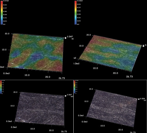
Figure 5. Initial grinding (120 grit) of a sample mounted in epoxy using two different wheel speeds (150 and 300 rpm). (a) and (c) Sample ground at 300 rpm, (b) and (d) sample ground at 150 rpm. The images were taken using an optical microscope at 500X.
Images after the initial grinding (Figure 5) indicate there is slightly more damage on the sample ground at 300 rpm. The effect of the initial grinding is more obvious on the samples ground at 1200 grit (FIGURE 6). The surface seems more uniform for the sample ground at 150 rpm and less even on the sample ground at 300 rpm. These results are consistent with the initial surface contours obtained using the profilometer, as uneven grinding was observed presumably due to the inhomogeneous nature of the material.

Figure 6. Samples ground up to 1200 using two different wheel speeds (150 and 300 rpm). (a) sample ground at 150 rpm, and (b) sample ground at 300 rpm. The images were taken using an optical microscope at 500X.
Polishing. Mechanical polishing removes material with a cutting mechanism similar to grinding. The scratches produced during polishing are shallow, and the prevalent mechanism of scratching is deformation.4
In the case of chemical-mechanical polishing, the liquid in the polishing suspension is chemically active. The abrasive particles constantly remove the formed protective film, creating a more uniform defect-free surface.4 Colloidal silica and alkaline alumina suspensions are an example of chemical-mechanical polishing suspensions used regularly in metallography.
Usually polishing involves the use of smaller particle size abrasives in suspensions on napless polishing cloths.2 The initial polishing steps should be designed to achieve maximum material-removal rates to eliminate the scratches and surface deformation created during grinding.4 Typically, the highest removal rates are obtained using diamond abrasives. Experimentation is required to determine the optimal parameters for grinding and polishing.4
The intermediate polishing steps should create a nearly defect-free surface at 100X, as seen in FIGURE 7. The final polishing step is used to eliminate the rest of the artifacts created during the previous steps.4

Figure 7. Profilometer images for a sample ground/polished up to (a) 500 grit (1 min) and (b) 1200 grit (20 s). Note that the surface seems fairly uniform, and the difference in height drops from 15.49µm to 8.39µm.
During final polishing a very low vertical force and low wheel speeds are required. Use of high or low nap polishing cloths can create rounding on the resin-fiber interface and should be avoided.2
Damage from deformation can extend beneath the scratches and create artifacts that need to be removed before inspection. Therefore, even when the abrasion scratches are removed, deformation damage can still be present after the final polishing. Softer materials are particularly sensitive to this type of damage and can show abrasive artifacts on the final surface. In some cases, additional polishing can help eliminate the damage.4 However, extended polishing times might enhance erosion of the different phases and fiber edge rounding in the case of composite materials.2
Some of the most common grinding polishing artifacts are scratches, fiber pull-out, matrix smears, streaks, erosion of different phases, and fiber and sample rounding and relief.4 FIGURE 8 shows images before and after ion milling of a coupon. An initial inspection using a scanning electron microscope (SEM) shows parallel scratches on the surface (a). The scratches were located on the glass and at the resin. The milled area revealed damage on the glass fiber. The damage on the glass fiber was at least 5µm deep. The scratches observed at the surface were parallel and possibly originated during either sectioning or the initial grinding.
If we assume the depth of material removed by the abrasive is proportional to the particle size, then the final polishing (1µm diamond) would not be sufficient to remove the damage created during previous steps. Moreover, the large differences of hardness between the glass fibers and the resin matrix can intensify uneven material removal during grinding and polishing. As seen in Figure 6, lower speeds on the polishing wheel can help create more shallow scratches and minimize the effect of the differences in hardness of the polymeric matrix and the glass fibers.

Figure 8. Selected area of polished surface for focused ion beam (FIB). Damage on the fiber glass was observed after ion milling.
To avoid creating sectioning and/or grinding artifacts, the microsectioning procedure needs to be tailored for each resin system. The process needs to account for the system’s hardness and fragility, as not all thermoset resins have the same mechanical properties. Polyimides, for instance, tend to be very fragile, and inadequate sectioning and grinding techniques can create artifacts that can be misinterpreted as defects.
References
1. George F. Vander Voort, Metallography: Principles and Practice, ASM International, 2000.
2. B.S. Hayes and L.M. Gammon, Optical Microscopy of Fiber-Reinforced Composites, ASM International, 2010.
3. L.E. Samuels, Metallographic Polishing by Mechanical Methods, ASM International, 2003.
4. G.F. Vander Voort, “Mechanical Grinding and Polishing,” ASM Handbook, vol. 9: Metallography and Microstructures, ASM International, 2004.
, is analytical services laboratory manager at Isola Group (isola-group.com); is senior director, ASL; is chemist, cross-sections specialist, and is ASL engineer; This email address is being protected from spambots. You need JavaScript enabled to view it..


