Advanced Glass Reinforcement Technology for Improved Signal Integrity
New glass fabrics promise to resolve challenges in high tech PCB design and fabrication.
Among the many challenges facing the electronics industry today are
those related to the need for increased speed. These challenges include
improved signal integrity and increased product reliability at
multi-GHz clock rates with inherently smaller threshold voltages and
picosecond rise/fall times. The implication of increased speed
continuously challenges the industry.
In recent
years, numerous technical papers have proposed methods to deal with
these challenges, coining the phrase “fiber weave effect” or FWE to
describe one of the central issues associated with the influence of the
glass reinforcement fiber on the electrical performance of the PCB1-7.
While many solutions have been presented to deal with FWE, none have
addressed the actual woven glass fabric in the laminate material. The
questions posed are these: Can an innovative glass fabric technology
improve end product performance? Can a raw material so far back in the
supply chain have an impact on leading edge industry challenges?
The
answer to both questions is Yes. A new high performance glass fabric
technology has been developed that demonstrates uniformity of glass
weave resulting in a homogeneous reinforcement layer. Used with readily
available resin technologies, this new glass fabric can provide
improved physical properties (laser and mechanical drilling,
dimensional stability and surface smoothness), superior electrical
properties (CAF resistance), and enhanced performance properties (more
uniform Dk and circuit impedance, reduced signal skew, and improved
signal integrity).
Many solutions have been
proposed to address FWE in circuit boards, however, in all of these
approaches there has been an implicit assumption that the glass fabric
reinforcement layer itself cannot be improved upon. This assumption is
not true. Consider a Style 1080 fabric, perhaps the most commonly used
glass fabric in high performance multilayer PCBs. The standard
construction of this style involves 60 yarns per inch in the warp or
machine direction and 47 yarns per inch in the weft or cross-machine
direction. The 1080 designation also specifies the type of yarn, as per
IPC-4412A9.
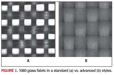
Figure 1 shows standard 1080 (a) and the high performance 1080 (b). Both have been made according to the IPC specification. Each has exactly the same quantity of glass with the same number of warp and weft yarns. The most obvious physical difference between these fabrics is the spread out ribbon-like yarns in the right-hand photo. To determine the properties of these fabrics, we must first understand the underlying technologies.

In
the manufacture of traditional fiberglass, the yarns are coated with a
vegetable-based starch-oil mixture to facilitate weaving. This coating
is then removed in a lengthy heat clean step, after which the yarn
bundle receives a silane coating. Depending on the tightness of the
weave and/or any ash residue left from the heat cleaning, the
individual yarns may or may not be fully wetted by the resin matrix. In
addition, the heat-cleaning step reduces the glass fabric strength by
approximately one third. Therefore, elimination of this damaging step
will create a stronger, more dimensionally stable composite.
Direct
application of a final resin-compatible finish during the fiber-forming
process provides a better interface between the glass fiber
reinforcement and the resin matrix8. This resin-compatible
finish is applied to the pristine surface of individual glass fibers
immediately as they are formed, remaining on the yarn and glass cloth
throughout the manufacturing process.
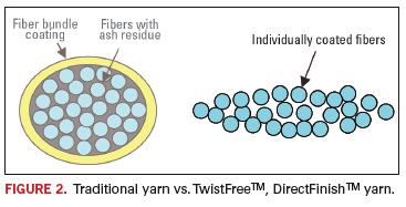
Another significant difference is seen in Figure 2, where the contrasts between a twisted fiber bundle and the more advanced untwisted yarn are highlighted. Traditionally, the glass fiber bundle is twisted to give strength and mechanical integrity to the yarn and make it easier to weave into fabric. Twisted yarns are somewhat rope-like, making thicker cross-points in the glass fabric (often referred to as knuckles). Twisted glass fiber is also known to contribute to stresses within the laminate.

Untwisted
yarn is more ribbon-like, lies flatter and spreads out easily. This
yarn construction yields a more consistent fabric, where glass fibers
are more uniformly distributed, and weave knuckles and open areas are
minimized.
Refer again to Figure 1, which shows two
different fabrics with the same amount of glass, but with the glass
fibers distributed differently. The traditional glass reinforcement
(Figure 1a) is thicker and unevenly distributed, leading to
inconsistent substrate properties. There are essentially three
differing glass thicknesses in the fabric: areas with two layers of
yarns (at the knuckles), areas with just one layer, and the interstices
between the yarns where there is no glass. In Figure 1a these areas are
very distinct from each other, while in Figure 1b the fibers have been
spread out to fill the interstices.
Figure 3 further illustrates this concept. For the best mechanical, electrical and performance properties, total glass uniformity is key. This is a direct result of maximizing the amount of two-layer coverage. In Figure 3 we have quantified the amount of zero, one and two-layer coverage using red, yellow and green areas (respectively) overlayed onto the photos from Figure 1. The percentages shown are based on measurements from the photographic images.

Considering that these
two fabrics contain the same amount of glass, it can be presumed that
the fabric in Figure 1b is thinner than 1a, and this is indeed the case
as confirmed by measuring total fabric thickness9. In fact,
the two-layer areas of glass in the traditional fabric are
approximately 50% thicker than the two-layer areas in the advanced
glass on the right (2.1 mils vs. 1.4 mils).
In
addition to a more uniform glass configuration, this new glass fabric
utilizes a lower dielectric constant (Dk) glass composition to reduce
the Dk difference between glass and resin. This Dk difference is at the
root cause of FWE. In traditional 1080 fabric using E-glass, the Dk
difference between the glass and high performance resin is
approximately 4 units. With the new fabric this Dk difference is
reduced by half. When the lower Dk is combined with smoother fabric,
the FWE can be significantly reduced.
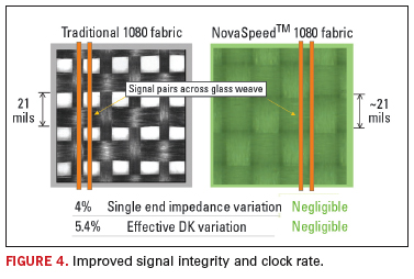
In Figure 4, the photos from Figure 1 have been overlayed with 3-mil lines to approximate scale for illustration purposes. Both fabrics have the same amount of glass but it is distributed differently. Estimates of single end impedance and effective Dk variation for traditional 1080 fabric are based on data presented in a paper by Brist et al at IPC Expo 20042.

Among
the many proposed solutions to address FWE is the use of a heavier
fabric style that has a balanced construction and tighter weave that
can reduce the open spaces7. However, addressing the issue
by glass style alone does not improve upon the other important aspects
discussed above. Indeed, laminate core thickness below about 4 mils
cannot be achieved using these heavier fabric styles.
Test Results
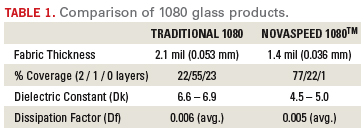
Table 1
shows initial test data on glass fabrics. The thickness measurements
are per ASTM D579 (25 psi). Dielectric constant (Dk) and dissipation
factor (Df) for the NovaSpeed 1080 fabric was measured at 10 GHz using
the NIST split cavity method at the Materials Research Lab at
Pennsylvania State University10. These measurements were
subsequently corroborated by calculations from test laminates per
IPC-TM-2.5.5.5 (stripline method). The traditional 1080 Dk and Df
measurements were taken from a table compiled by the IPC 3-12d Glass
Reinforcement Task Group and represent data from four global
manufacturers of E-glass yarn11.

As
previously described, the Dk of the NovaSpeed glass fabric is lower
than that of E-glass in traditional fabric. More precisely, the Dk of
this fabric is midway between that of E-glass and typical high
performance resin systems. Thus the Dk difference between glass and
resin is half of that seen in typical laminate products.
Table 2 shows Dk and Df results at 10 GHz with the low Dk 1080 glass fabric alone, and with three commercially available resin systems. These resin systems, while high performance, are not characterized as “exotic” but are considered to be “FR-4 processable.” The bulk glass measurements were done using the NIST split cavity method and all other measurements are per IPC-TM-650 2.5.5.5 stripline method.

Conclusion
Based
on the known characteristics of this advanced glass fabric, direct
improvements can be predicted. The flat, smooth laser-drillable glass
fabric will have improved laminate surface planarity and inherently
lower surface roughness, as compared to laminate made with traditional
glass fabrics. Improvements in “telegraphing,” laser-drilled hole
geometry, hole plating quality and laser drilling speed can be
expected. Where mechanical drills are used, a reduction in drill wander
can also be expected. Furthermore, the high strength properties of a
directly finished fabric, combined with the more uniform distribution
of the glass fiber yarns, provides improved dimensional stability in
circuit board laminate applications.
The use of a direct finishing technology combined with the spread fibers of untwisted yarn results in greatly improved wettability and resin impregnation (of the glass bundles), and therefore the highest quality glass-to-resin bond is ensured. This property is the main factor in improved CAF resistance. An electrochemical migration phenomenon similar to CAF is caused by hollow fibers. This low Dk glass fabric exhibits zero hollow fibers. Table 3 summarizes these characteristics with corresponding quality and reliability improvements.

Table 4 identifies performance improvements that result in the fabric with the combination of an improved finishing method, a non-twist glass, and a proprietary low Dk glass formulation. The printed circuit substrate exhibits a homogeneous Dk and Df, leading directly to less impedance variation and reduced signal skew, resulting in improved signal integrity.

An advanced glass fabric has been utilized
in several high performance commercial resin systems to generate test
panels with superior electrical properties at 10 GHz. However, by using
a unique manufacturing process and proprietary low Dk glass
formulation, a homogeneous reinforcement layer has been developed that
is unlike traditional glass fabrics. In fact, the key features of this
proprietary technology are not addressed by existing industry
specifications.
It is expected that FWE can be
completely eliminated as a performance constraint in high speed PCB
susbstrates with the use of this novel technology. This new glass
fabric could represent a paradigm shift for PCB substrate performance. PCD&F
Russell S. Dudek Jr. is a technology specialist at Compunetics; This email address is being protected from spambots. You need JavaScript enabled to view it.. John J. Kuhn is VP and CTO and Patricia Goldman is manager, technical services, at Dielectric Solutions; This email address is being protected from spambots. You need JavaScript enabled to view it., This email address is being protected from spambots. You need JavaScript enabled to view it..
REFERENCES
1. K. Dietz, “Fine Lines in High Yield (Part XCVIII): Advances in Reinforcement Structures,” TechTalk in CircuiTree, November 2003.
2. G. Brist, B. Horine, G. Long; “High Speed Interconnects: The Impact
of Spatial Electrical Properties of PCB due to Woven Glass
Reinforcement Patterns,” S18-5-1, IPC Expo/SMEMA Council/APEX/Designers
Summit 2004.
3. E. Bogatin, S. Zimmer, “Achieving Impedance Control Targets,” Printed Circuit Design & Manufacture, April 2004.
4. S. McMorrow, C. Heard, “The Impact of PCB Laminate Weave on the
Electrical Performance of Differential Signaling at Multi-Gigabit Data
Rates,” DesignCon East 2005.
5. E. Bogatin, “Skewering Skew,” Printed Circuit Design & Manufacture, April 2005.
6. J. Loyer, R. Kunze, X. Ye, “Fiber Weave Effect: Practical Impact Analysis and Mitigation Strategies,” CircuiTree, March 2007.
7. L. Ritchey, “Intelligent Design,” CircuiTree, April 2007.
8. J. Kuhn, “Advanced Reinforcement Technology Presents New Design
Opportunities for Printed Circuit Boards”, ECWC 10 Conference at IPC
Printed Circuits Expo/APEX/Designers Summit 2005.
9. IPC-4412A, “Specification for Finished Fabric Woven from “E” Glass
for Printed Boards,” January 2006, IPC, Bannockburn IL..
10. NIST Split Cavity method for measurement of relative permittivity
[Dk] and loss tangent [Df], subsequently standardized as IPC-TM-650
2.5.5.13.
11. Committee Report of Woven Glass Reinforcement Task Group 3-12d from
IPC Apex/Expo 2007 (ipc.org/CommitteeDetail.aspx?Committee=3-12D).


