ECAD-MCAD Design Integration
As design disciplines converge, the ability to display, exchange and work in 3D will become an essential part of the electronic product development process.
In today’s global market, the
pressure to create smaller, more intelligent products in less time is
forcing design engineers to critically reassess and revise the overall
product design process – from concept right through to manufacture.
The
need for change is further fueled by the rapid development of
electronics technology, which in a series of evolutionary steps has
altered the fundamental processes we use to create today’s electronic
products. The emerging challenge for product development teams is
managing and working with these increasingly interdependent processes
while meeting production deadlines.
As electronic
products and the processes used to create them evolve, the
fundamentally dissimilar worlds of electronic and mechanical design
need to work in harmony. To stay competitive in today’s market,
designers must adopt systems that unify the design process and allow
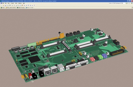
the smooth flow of design data across the electromechanical divide (Figure 1).
|
|
Electronics
design, however, is typically viewed as a set of disparate design
disciplines; each requiring their own design environments -- hardware
design, programmable logic design and software development. This
divisive approach hampers efficient collaboration with the wider
product development process. Unifying electronic design, however,
creates the environment required for true design interaction and
collaboration in all stages of electronic design flow. By incorporating
the processes needed in a single application, a unified electronic
development system shares design data at a native level and manages
design information globally. The seamless flow of information between
design stages opens the door to flexible, interactive and innovative
design practices that support a fluid division between hardware and
software.
The efficiencies and high level of design
collaboration delivered by a unified electronic product development
system extend to all levels of the design flow – from concept though to
manufacture. The central control of design information and data allows
all those involved in the product development process to work in a
connected and collaborative way, all the way through to document
handling, parts management and manufacturing.
In the
bigger picture, the need for effective design collaboration extends to
those outside the immediate sphere of electronic design. An
increasingly important part of the evolution in product development is
interaction between the electronic and mechanical aspects of a design,
where the incessant need for smaller and more functional packaging
forces the two to be intimately connected – in both a physical sense
and in development.
Board assemblies now typically
hold all of the external hardware such as connectors, keypads and
displays, while the product case assembly neatly exposes these to the
user. Gone are the days when a product case merely housed the
electronic assemblies and the separate hardware elements were connected
via interwiring. In short, packaging has now moved from being a simple
container to a tightly integrated part of the product.
Converging MCAD-ECAD Design
More
than ever before, a product’s packaging must take into account the
physical aspects of the internal electronics while, in turn, the
electronics assembly – in practice the board design – must allow for
the physical style and functionality of the package design. This
increased interdependency of design processes is in line with the
overall trend in electronic product development where previously
isolated stages in the design flow must now efficiently interact. From
design capture through to manufacturing, maintaining a competitive edge
in the market requires tools and processes that support collaboration
at all levels of development.
Efficiently bridging
the gap between the mechanical and electronic design processes is,
therefore, becoming crucial for collaborative and successful product
development. However, rather than simply passing raw dimensioning and
positional data from the ECAD to MCAD environment, what is needed is a
design tool that allows a bi-directional flow of comprehensive 3D data
between those domains. In the ECAD world, this means an ability to
import and seamlessly integrate 3D component data from an MCAD
environment; then pass a full and accurate 3D representation of the
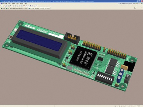
board assembly back to the MCAD domain (Figure 2).
|
|
This
higher-level process also offers the opportunity of passing
comprehensive, component-inclusive board data to the mechanical design
environment earlier in the product development cycle, allowing
ECAD-MCAD co-design. What’s more, the gain in design flow efficiency is
further enhanced by the reduced need for a prototype board assembly to
be on hand during the MCAD design stage. With comprehensive 3D data
exchange, the mechanical designer can have full dimensional information
on hand even if the board is still being routed in the ECAD environment.
To
harness this potential and prepare your design system for the ongoing
convergence in the MCAD and ECAD worlds, the minimum requirement is for
an electronics design system that allows 3D models to be imported and
attached to components. Such a system should also allow you to view and
export an accurate 3D rendition of a complete board design. Ultimately,
this free exchange of 3D design data creates the opportunity for a high
level of interaction between the mechanical and electrical design
environments, promoting the productivity and innovation benefits of
MCAD-ECAD design collaboration.
Electromechanical Design Flow
As
electronic products shrink in size, production deadlines shorten and
the industry moves toward “soft” electronic design solutions, the
ability to efficiently share information across all design processes is
becoming crucial. A unified product development environment offers this
capability at a fundamental level through its ability to complete all
stages of electronic design – hardware, programmable hardware and
embedded software – within a single environment.
The
natural extension of this unified data-sharing concept is to encompass
the 3D modeling data that must pass to and from the mechanical design
domain. In practice, this means implementing ECAD and MCAD systems that
support 3D data exchange at a high level, which draws the environments
together to create a holistic design environment and more efficient
product development workflow.
This approach is
gaining rapid momentum. Take, for example, R&D design-house 3G
Engineering, which has embraced ECAD-MCAD integration to simplify the
overall design process while reducing the company’s design turnaround
times and product development costs. As a specialist in the development
of custom-built turnkey electromechanical products for industry, 3G’s
in-house electronic and mechanical design processes are highly
interdependent and need to be approached as a single, cohesive task.
3G
Engineering’s consolidated workflow is based on a unified ECAD system
that supports both 3D modeling and the bi-directional exchange of 3D
design data.
The ECAD system can bring together the
software, hardware and programmable hardware parts of the design
process into a single application and has allowed the 3G engineers to
draw the company’s MCAD system into the overall product development
process. The result is a homogeneous workflow that allows a high level
of interaction between the ECAD and MCAD design environments.
The
data exchange capability is used to good effect by 3G engineers who
first develop and refine a new project’s physical properties in the
MCAD environment, then determine the volumetric dimensions of the space
available for its electronic subsystems. These preliminary dimensions
are transferred to the ECAD environment – generally as a proposed 2D
board shape – very early in the design cycle, so the board layout
process can proceed in parallel with the MCAD design work.
The
board assembly is subsequently developed using components with matching
3D models that are sourced from the parts manufacturers or, if
unavailable, created from scratch in an MCAD environment. These custom
3D representations are transferred to an ECAD system as STEP 3D data
files, where they can be attached to the matching components in the
system’s libraries. 3G Engineering is progressively building the 3D
elements within the company’s ECAD libraries but sees this as a future
investment that easily justifies the work involved in collecting and
creating 3D component models.
Ultimately the fruits
of that labor become apparent when a board assembly has all components
in place. At this point, the 3G engineers can create and view a
meaningful 3D representation of the board assembly in the ECAD system,
then transfer that rendered image into MCAD as a STEP 3D data file. The
3D representation is then checked for 3D dimensional accuracy in the
MCAD environment where, almost literally, it can be fitted into the
product’s enclosure or allocated cavity space. According to 3G, at this
point, there is rarely a need for design revisions to correct for
physical discrepancies between the electrical and mechanical assemblies
because, thanks to the initial flow of accurate 2D/3D data, the
engineers are able to simply “get it right the first time.”
By
basing its product development process on a unified ECAD solution that
smoothly interconnects to the MCAD environment, 3G Engineering is able
to tackle product design as a single engineering challenge, rather than
as set of disconnected design problems that are resolved in isolation –
and finally brought together. The company’s engineers can confidently
develop the ECAD and MCAD elements of a design in parallel, ECAD-MCAD
amalgamation errors are rare, and the overall product design process is
faster and simpler. According to 3G, design processes that formerly
took weeks with the disconnected ECAD-MCAD systems used in the past can
now be completed in just days – a considerable asset for a company that
holds a competitive advantage based on innovation and rapid product
development times.
As ECAD and MCAD design
disciplines converge, it is becoming increasingly important for all
design engineering teams to take into account how that relationship
works and its ultimate effect on the overall product development
process.
For those accustomed to working in the
traditional 2D space of ECAD design capture and board design, it is now
important to consider the benefits of embracing the 3D design space and
its connection with the entire production chain. The ability to
display, exchange and work with 3D rendered objects in your electronic
design system is not just a nice add-on feature set and is certainly
not a gimmick. As design disciplines converge and collaborate at a
higher level, it has become an inherent and essential part of the
electronic product development process that will play an increasingly
important role into the future. PCD&F
Rob Evans is in technical marketing with Altium Ltd. He can be reached at This email address is being protected from spambots. You need JavaScript enabled to view it..


