Ink Jet Printing for High-Frequency Electronic Applications
Nanoparticle inks and drop-on-demand ink jet printers offer a unique opportunity to generate fine-line additive circuits on flexible, three-dimensional substrates.
Ink jet printing has been gaining interest for use in electronics
manufacture. This article is intended to provide a brief overview of
ink jet printing; a review of some of the applications of
high-frequency electronics from the literature; and, finally, some
ideas as to possible further applications.
In a review of ink jet printing for graphics applications, Le
defined the technology as follows; “Ink-jet is a non-impact dot-matrix
printing technology in which droplets of ink are jetted from a small
aperture directly to a specified position on a media to create an image1.”
To
facilitate this technology, there are two general designs of ink jet
printers. The designs are continuous and drop-on-demand (DOD). As the
names imply, these designs differ in the frequency of generation of
droplets.
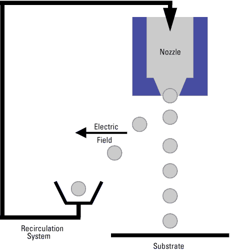
In continuous ink jet printers, droplets are generated continually
with an electric charge imparted to them. As shown schematically in Figure 1,
the charged droplets are ejected from a nozzle. Depending upon the
nature of the imposed electric field, the charged droplets are either
directed to the media for printing, or they are diverted to a
recirculation system. Thus, while the droplets are generated
continuously, they are directed to the media only when/where a dot is
desired.
|
|
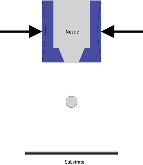
In DOD ink jet printers, droplets are generated only when they are
needed. The droplets can be generated by heating the ink to boil off a
droplet (so called thermal ink jet). Alternatively, the droplets can be
ejected mechanically through the application of an acoustic pulse or
electrically stimulating a piezoelectric to elicit a deformation, which
will generate a droplet as shown in Figure 2.
|
|
An advantage of ink jet printing is its modularity. Individual
printing nozzles are combined into a single print head. Multiple print
heads can be combined within a single printer. This allows printing
more than one ink at a time (e.g., different colors). The modular
nature also allows for combining printheads laterally for use in large
area printing. Currently, a major application for ink jet printing is
in the production of billboards.
Inks for Printing Electronic Products
To apply
ink jet printing technology to electronics, the ink to be printed is
made up of electronic materials rather than the pigments used in
graphics printing. As with other fluid-based printing methods, the ink
used in ink jet printing is a complex formulation of solvents,
plasticizers and surfactants in addition to the appropriate electronic
materials. For the most part, DOD printers have been used in ink jet
printing of electronics.
Ink jet printing has been used to produce conducting and semiconducting polymers2, as well as displays3.
The work discussed here will concentrate primarily on ink jet printing
of conductors. Work has been reported on ink jet printing of copper4, silver5 and gold6.
Typically, nanoparticles of the desired conductor are dispersed in the
ink. However, due to the high surface area of copper nanoparticles,
oxidation becomes a concern. This necessitates using inks containing a
copper metal precursor, rather than copper nanoparticles. Commercially
available silver or gold inks can be obtained from several companies
such as Cabot (U.S.), Cima NanoTech (Israel/U.S.), Ulvac (Japan),
Harima Chemical (Japan) and Advanced NanoProducts (Korea). These inks
contain up to 60% by weight of metal.
The small
particle size of the nanoparticles in electronic inks allows for lower
firing temperatures to densify the printed ink. Silver nanoparticles
fired as low as 260˚C have resulted in dense films with conductivity
about 50% of bulk silver7. This low densification
temperature allows for circuits on plastic substrates that could not
otherwise handle the higher temperatures typically used to densify
metallic particles.
Ink Jet Printing for Electronic Products
There
are many advantages to employing ink jet printing for electronic
circuits, several of which are listed below. The first four are
currently being utilized. The others are potential advantages that, to
the author’s knowledge, have not yet been exploited for electronic
applications.
Digital process. Ink
jet is a dot-matrix technology, a digital process. This means that
patterning can be directly computer controlled. No masks or screens are
necessary. Changes can be made quite easily by altering the
computer-controlled pattern rather than awaiting a new mask or screen.
Additive process.
Materials are applied only where desired. This can be important when
expensive materials are being deposited. Additionally, the extra steps
and environmental concerns of stripping are eliminated with ink jet
printing.
Non-contact. The print
nozzles do not contact the substrate, preserving delicate surfaces.
They are typically positioned 0.5 to 1.0 mm above the substrate.
3-D printing. Through
programming of the individual nozzles and repeated passes, it is
possible to vary the thickness of the deposited ink with position. This
has been used in forming 3D ceramic structures8 and to print spiral conductors9.
Different materials can be printed simultaneously.
As with multicolor printing of graphics, it is possible to print
different electronic materials (e.g., conductors, resistors,
dielectrics) simultaneously. By ganging printheads containing the
different materials, it would be possible to print them in a single
pass. This could eliminate the need for pattern registration for
subsequent depositions and increase throughput.
Large sizes.
As mentioned above, ink jet printing is currently used in the graphics
world to print billboards. The same print heads that are used in
desktop printing of electronic materials can be ganged laterally to
print onto significantly larger-sized substrates. It is important to
note that this scale up is direct, that is the printheads are the same,
so that the parameters found applicable at small sizes should be usable.
For
many electronic applications, screen printing has been the preferred
deposition method. The line widths and line spacing typical of ink jet
printing are one-half those typical of screen printing: 30 µm vs. 60 µm10. Even finer geometries have been reported in developmental ink jet printing: 10 µm lines and spacing11.
While
there are advantages to ink jet printing of electronics, there are
drawbacks. The physics of generating droplets from very narrow diameter
nozzles constrains the allowable ink rheology. The ink typically needs
to have a surface tension >35 mN/m and a viscosity of 1 to 10 cPoise12.
In part because of these rheological constraints and the present
limited market, there are not many commercially available inks for
electronics. However, it is anticipated that as the market grows,
additional suppliers and ink compositions will become available.
High-Frequency Applications
Reports of ink jet printing used in high-frequency electronics are
reviewed below to give a sense of the breadth of applications possible.
Radio-controlled watch module. Seiko
Epson has reported fabricating 20 metal layer circuit boards of 200 µm
thickness (not including the base polyimide substrate) by ink jet
printing using a piezoelectric DOD printer13. The boards
measured 20 x 20 mm. Silver conductor lines and vias were ink jet
printed as were the interlayer dielectrics. The silver conductor lines
were 4 µm thick and 50 µm wide with a minimum spacing of 110 µm. No
details of firing conditions were reported.
By using
this technology, the module size for radio-controlled watches was
reduced by 65% over a chip-on-board (COB) process using a glass-epoxy
substrate. The ink jet PCB contained all of the passive components
except for the antenna, connector and crystal.
Co-planar waveguides in PCBs. Joint work carried out by Motorola and the University of Illinois (Chicago) studied the possibility of using ink jet printing to form PCBs. For one of the test vehicles, they used a DOD printer to fabricate coplanar waveguides consisting of silver transmission lines between copper etched ground planes and signal pads on polyimide14. The conductor line was densified by heating at 300˚C for 15 min. Their lines were 120 to 200 µm wide and 1 to 3 µm thick.
The resistivity of the conductor lines was 3.5 x 10⁻⁵ Ωcm.
They
found good, repeatable electrical results between 0 to 4 GHz. They also
found that test vehicles subjected to 85% humidity and 85°C for up to
172 hours showed an average increase of only 4% in the resistivity of
ink jet printed silver conductors on polyimide.
RFID components.
Researchers at the University of California–Berkeley have been active
in fabricating RFID components via ink jet printing. They have printed
nanoparticles of gold onto polyester, creating spiral inductors and
conductors using a DOD printer15. To improve the uniformity
of the printed conductors, they overlaid drops of ink with 5 to 15 µm
spacing. They then printed several lines on top of each other. To
further increase line uniformity, they printed with the substrate
heated to 160˚ to 190˚C.
Using their print
conditions, the best results were found for printing three layers or
more. The resultant conductors were about 160 µm wide and had
resistivity as low as 23 mΩ/n. They also used ink jet printing to
deposit polyimide dielectrics for crossovers and capacitors. Pin-hole
free dielectric films were formed as thin as 340 nm and as thick as 3
µm. Spiral inductors of 350 nH were formed with three printed layers of
gold. The inductors had radii of 5,000 µm with line widths of 160 µm
and line spacing of 100 µm.
Transmission lines for cell phones. Nokia
has investigated the possibility of using ink jet printed conductors on
polymers for possible use in cell phones and other electronic devices.
They printed silver nanoparticles onto polymer substrates using a DOD
printer16. They printed several different sized conducting
traces and cured them in an infrared oven. For thin conductor lines
(<10 µm), they found the optimal curing conditions to be 240˚C for
60 min.
To test the electrical parameters of the
ink, they fabricated 50 Ω transmission lines on ceramic substrates.
They compared transmission lines with ink jet printed silver conductors
to etched copper lines. The line width and length were the same for the
two conductors. The thickness of the ink jet printed conductor was 2
µm, while that of the etched copper was 17 µm. The insertion losses
between 0 to 5 GHz were slightly larger for the ink jet printed silver
conductor but were judged to be acceptable.
Future Applications
Hopefully,
the applications described above demonstrate the applicability of ink
jet printing for high-frequency electronic products.
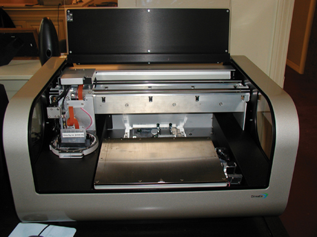
Using a tabletop dedicated materials deposition system from Dimatix17, shown in Figure 3,
product development on additional applications of ink jet printing is
ongoing at Advanced Materials Solutions. The Dimatix system has a 200 x
300 mm printing area with a vacuum platen that is heatable to 60°C. The
system has integrated fiducial and drop watcher cameras. It can be used
to print Ag and AgCu conductors onto Mylar, ceramic and textile
substrates.
|
|
The printer uses replaceable cartridges, which avoids any cross
contamination of inks. The cartridges have silicon MEMS printheads
containing 16 independently controllable nozzles. The printhead can be
heated up to 70°C. The nozzles have 21 µm orifices and 254 µm spacing
(100 dpi). The cartridges are user fillable. The following applications
are under development.
Quickturn Antenna Prototypes
As has been
described, ink jet printing is a digital process. No masking is
necessary, only a digital file. This could lead to quick production of
prototypes, such as antennas. It would allow for a quick turnaround for
changes. We envision an iterative process in which a prototype can be
printed from a digital file, tested and proposed changes to the pattern
introduced digitally. This cycle would then be repeated until the
desired characteristics were obtained. Delays associated with waiting
for new masking or screens to be produced could be eliminated while
optimizing the design.
Conformable Circuits
Ink
jet printing can be performed on flexible substrates. These substrates
could be bonded to a non-planar surface to permit conformable circuits.
(It should be pointed out that the flexibility of the densified
conductor traces has not yet been demonstrated.) Alternatively, with a
change of fixturing, it may be possible to print directly onto
non-planar surfaces.
Circuits on E-Textiles
E-Textiles are textiles into which metal wires are woven. There has been work done on using these for transmission lines18.
By ink jet printing additional conductors and passive components, more
advanced capabilities can be built-in with the integral conductors
acting as interconnects. Potential applications include wearable
electronics (e.g. GPS or antennas), physiological monitors and animal
monitoring via RFID. Conductive traces have been successfully
demonstrated on E-textiles via ink jet printing19.
Conclusion
This
article was designed to provide an introduction to the applicability of
ink jet printing in the electronics industry. The utility for several
high-frequency applications has been demonstrated. It is hoped that
this article will stimulate the reader to consider other possible
applications of this exciting technique. PCD&F
John Blum is Principle, Advanced Materials Solutions LLC. He can be contacted at This email address is being protected from spambots. You need JavaScript enabled to view it..
References
1. H.P. Le, Progress and Trends in Ink-jet Printing Technology, Journal of Imaging Science and Technology, Vol. 42, No. 1, pp. 49-62, [1998].
2. B.J. de Gans, P.C. Duineveld, U.S. Schubert, Inkjet Printing of Polymers: State of the Art and Future Developments, Advanced Materials, Vol. 16, No. 3, pp. 203-213, [2004].
3. M.L. Chabinyc, W. S. Wong. A.C. Arias, S. Ready, R.A. Lujan, J.H.
Daniel, B. Krusor, R.B. Apte, A. Salleo, and R.A. Street, Printing
Methods and Materials for Large-Area Electronic Devices, Proceedings of the IEEE, Vol. 93, No. 8, pp. 1491-1499, [2005].
4. G.G. Rozenberg, E. Bresler, S.P. Speakman, C. Jeynes, and J.H.G.
Steinke, Patterned low temperature copper-rich deposits using inkjet
printing, Applied Physics Letters, Vol. 81, No. 27, pp. 5249-5251, [2002].
5. P.J. Smith, D.Y. Shin, J.E. Stringer, B. Derby, and N. Reis, Direct
ink-jet printing and low temperature conversion of conductive silver
patterns, Journal of Materials Science, Vol. 41, pp. 4153-4158, [2006].
6. J. Chung, S. Ko, N.R. Bieri, C.P. Grigoropoulos, and D. Poulikakos,
Conductor microstructures by laser curing of printed gold nanopartricle
inks, Applied Physics Letters, Vol. 84, No. 5, pp. 801-803, [2004].
7. D. Kim, S. Jeong, J. Moon, and K. Kang, Ink-Jet Printing of Silver Conductive Tracks on Flexible Substrates, Molecular Crystals and Liquid Crystals, Vol. 459, 45/[325] – 55[335], [2006].
8. K.A.M. Seerden, N. Reis, J.R.G Evans, P.S. Grant, J.W. Halloran, and
B. Derby, Ink-Jet Printing of Wax-Based Alumina Suspensions, Journal of the American Ceramic Society, Vol. 84, No. 11, pp. 2514-2520 [2001].
9. J. Mei, M.R. Lovell, and M.H. Mickle, Formulation and Processing of
Novel Conductive Solution Inks in Continuous Inkjet Printing of 3-D
Electric Circuits, IEEE Transactions on Electronics Packaging Manufacturing, vol. 28, No. 3, pp. 265-273, [2005].
10. K. Kowai, Y. Kawamura, H. Nagata, S. Yamaguchi, T. Sakuma, K.
Sakurada, T. Kobayashi, and K. Wada, Low Temperature Co-fired Ceramics
Multi-layer Substrate Utilized with Ink-jet Printed Silver Layers, Proceedings of the 38th International Symposium on Microelectronics (IMAPS), pp. 823-833, [2005].
11. K. Murata, J. Matsumoto, A Tezuka, Y. Matsuba, H. Yokoyama,
Super-fine ink-jet printing: toward the minimal manufacturing system, Microsystems Technology, Vol. 12, pp. 2-7, [2005].
12. M.D. Croucher and M.L. Hair, Design Criteria and Future Directions in Inkjet Technology, Industrial & Engineering Chemistry Research, Vol. 28, pp. 1712-1718, [1989].
13. H. Imai, S. Mizuno, A. Makabe K. Sakurada, K. Wada, Application of Inkjet Printing Technology to Electro Packaging, Proceedings of the 39th International Symposium on Microelectronics (IMAPS), pp. 484-490, [2006].
14. J.B. Szczech, C.M. Megaridis, D.R. Gamota, and J. Zhang, Fine-Line
Conductor Manufacturing Using Drop-on Demand PZT Printing Technology, IEEE Transactions on Electronics Packaging Manufacturing, Vol. 25, No. 1, pp. 26-33, [2002].
15. D. Redinger, S. Molesa, S. Yin, R. Farschi, and V. Subramanian, An Ink-Jet-Deposited Passive Component Process for RFID, IEEE Transactions on Electron Devices, Vol. 51, No. 12, pp. 1978-1983, [2004].
16. Z. Radivojevic, K. Andersson, K. Hashizume, M. Heino, M. Mantysalo,
P. Mansikkamaki, Y. Matsuba, and N. Terada, Optimised Curing of Silver
Ink Jet Based Printed Traces, Proceedings of the International Workshop on Thermal Investigations of ICs and Systems (THERMINIC), pp. 163-168, [2006].
17. Model 2831; FUJIFILM Dimatix, 2230 Martin Ave, Santa Clara CA 95050.
18. D. Cottet, J. Grzyb, T. Kirstein, and G. Troster, Electrical Characterization of Textile Transmission Lines, IEEE Transactions on Advanced Packaging, Vol. 26, No. 2, pp. 182-190, [2003].
19. J.B. Blum, Fabric Based Electronics, presented at Vermont EPSCOR Annual Conference, Burlington VT, [2007].


