ENEPIG Corrosion Mechanisms
Different types of nickel corrosion and potential mitigation strategies.
Electroless nickel immersion gold (ENIG) chemistries were introduced in the mid-1990s to replace electrolytic nickel and gold for high-density circuits. In the mid-1990s, nickel corrosion, soon to be known as the ubiquitous “black pad,” was discovered. Chemical suppliers and board manufacturers took steps to reduce the occurrence of black pad. To that end, in 2002, IPC released IPC-4552, “Performance Specification for Electroless Nickel/Immersion Gold (ENIG) Plating for Printed Boards.”
In the late 1990s, electroless nickel electroless palladium immersion gold (ENEPIG) chemistries were introduced as a universal finish for gold, aluminum and copper wire bonding, with perceived protection from black pad. In 2013, IPC released IPC-4556, “Specification for Electroless Nickel/Electroless Palladium/Immersion Gold (ENEPIG) Plating for Printed Boards.” Today, black pad is still a reality with ENIG and ENEPIG plating.
Electroless Nickel Deposition
The most common electroless nickel baths for printed circuit boards (PCBs) use a phosphorous-containing reducing agent, typically incorporating ≤10% phosphorous, by weight, in the nickel deposit. The nickel phosphorous (Ni-P) deposit is amorphous and has an isotropic surface energy. This produces a Ni-P deposit with hemispherical nodules that look like soap bubbles (Figure 1).
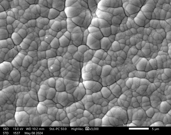
Figure 1. Hemispherical Ni-P nodules.
Nickel nodule growth conditions vary from nodule to nodule, so we see nodules of various sizes, as seen in Figure 1. As plating thickness increases, the nickel nodule hemispheres contact each other, forming cusps. Any two given nickel nodule nuclei are separated from each other by a distance of (D) units. Each nickel nodule has a given radius (r) for its size (Figure 2).
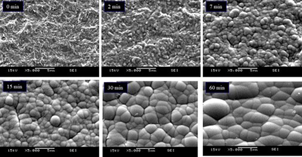
Figure 2. Nickel nodule hemisphere growth versus plating time.
There are inherent stresses at the cusp for any given two nickel nodules in contact with each other. The smaller the radii, the higher the stress. As plating thickness increases, the cusp stress at the two nodules decreases, and the propensity for boundary corrosion is reduced. The Cartesian coordinate system can model the distribution of cusp stresses.1
The ratio of r/D is critical.1 As the r/D ratio is increased, cusp stress is reduced, and boundary corrosion is suppressed. There are two ways to increase the r/D ratio: 1) increasing the thickness of the nickel deposit, which increases the radius (r) of the nickel nodules, and 2) increasing the number of nucleation sites by optimizing the cleaner micro-etch activator, and nickel initiation, which decreases the distance (D) between two given nickel nodule nuclei.
Nickel and Palladium Corrosion Mechanisms
The primary types of corrosion with ENEPIG deposits are catastrophic horizontal, nodule pits and boundary pits. All three types are galvanic corrosion. Galvanic, or bimetallic corrosion, is an electrochemical process in which one metal preferentially corrodes when in electrical contact with another in the presence of an electrolyte. Both nickel and palladium are subject to galvanic corrosion by gold. Stoichiometrically, this is shown in Equation 1 and Equation 2.
Ni0 + 2Au-1 🡪 Ni+2 + 2Au0
Eq. 1. Nickel, gold stoichiometry.
Pd0 + 2Au-1 🡪 Pd+2 + 2Au0
Eq. 2. Palladium, gold stoichiometry.
The explanation for nickel corrosion is that the nickel readily gives up electrons if there is an accepting species, in this case, gold. If gold is unavailable, as in the deep nodule boundaries, the hydrogen (H+) ions pick up the electrons and permit the nickel to corrode without gold deposition. In the case of ENEPIG, the difference in voltage in the electromotive force (EMF) series determines the driving force for the displacement reaction to proceed (Table 1).
Table 1. EMF Series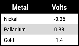
The driving force for the gold/nickel displacement is equal to +1.4 to -0.25 = 1.65V, while the driving force for the gold/palladium displacement is equal to +1.4 to +0.83 = 0.57V. Nickel is approximately three times more easily displaced than palladium. If pores are in the palladium layer, the gold will preferentially exchange with the underlying nickel, causing nickel corrosion at the palladium-nickel interface.
Catastrophic horizontal corrosion. The primary drivers for catastrophic horizontal corrosion are poor adhesion between the nickel and palladium layers, macro-cracks in the palladium deposit, or a thin/porous palladium deposit.2 Figure 3a shows horizontal corrosion with a 2µin palladium deposit and an exaggerated immersion gold time of 30 min., and Figures 3b and 3c show the effects of palladium macro-cracking. Milad found that 6-9µin of palladium was needed to negate nickel corrosion due to a thin/porous palladium deposit when coupled with exaggerated immersion gold times.2 The thicker palladium deposit likely reduces the palladium cusp stresses, too, but only to a certain point.
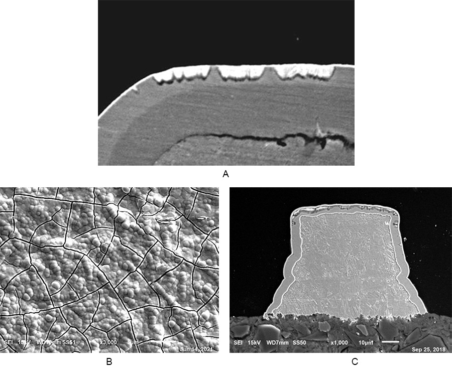
Figure 3. Various horizontal corrosions. (a) 30-min. gold time, (b) palladium cracks, (c) palladium crack corrosion.
Nodule and boundary pit corrosions. There are three primary drivers for pit corrosion: a thin/porous palladium deposit,2 micro-cracks in the palladium deposit, and hydrolyzed nickel species (NiOH+1) formation on the plated nickel deposit.3 Micro-cracks can form in the palladium deposit due to hydrogen embrittlement during the palladium plating. Hydrolyzed nickel species can form on the nickel nodules or at nickel nodule boundaries due to excessive nickel drip times and poor-quality rinsing. The hydrolyzed nickel species result in particles and nickel oxidation. When these particles form, there are increased stresses at the cusp for any given two palladium nodules in contact.
In general, the same nickel r/D ratio criticality also applies to the palladium deposit. The r/D ratio may be increased two ways: 1) increasing the thickness of the palladium deposit, which increases the radius (r) of the palladium nodules and reduces cusp stress, but only to a certain point, and 2) increasing the number of nucleation sites by optimizing the nickel bath parameters, drip time, rinsing and palladium initiation, which decreases the distance (D) between two given palladium nodule nuclei.
Pit corrosion can occur within or at a nickel nodule boundary. Figure 4a shows pit corrosion, and Figure 4b shows the seam in the palladium deposit providing a path to the nickel deposit, resulting in the corroded nickel area (bright white area).
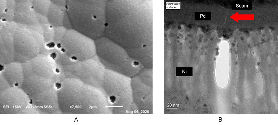
Figure 4. Nickel pit corrosion. (a) top-down view of pits, (b) palladium seam corrosion.
Energy-dispersive x-ray spectroscopy (EDS) was used to analyze the pit corrosion site in Figure 4b. There is clear evidence of the gold (Au) breaching through the palladium (Pd) and corroding the nickel (Ni). In the corrosion’s wake is the enrichment of oxygen (O) and phosphorous (P) (Figure 5). This can lead to solderability and wire bonding issues.
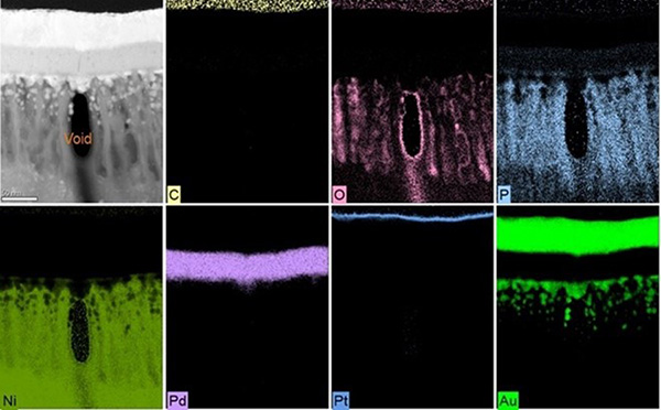
Figure 5. EDS of the pit corrosion.
Nickel seam corrosion. Pit corrosion can be traced back to hydrolyzed nickel species (NiOH+1) formation on the plated nickel deposit. Nickel seam corrosion is a specific type of boundary pit corrosion with a different origin. Instead of particles originating on top of the nickel deposit, particles originate at the bottom of the nickel deposit, in essence, on the base copper. These particles then create excessive stress at the nickel nodule boundary cusps, increasing the propensity for corrosion. The increased nickel cusp stresses transfer to the palladium deposit, completing the seam pathway. Particles that lead to nickel seam corrosion are due to poor copper surface preparation and insufficient surface cleaning; in some cases, over-aggressive micro-etching roughness can lead to nickel cusp stresses. Figure 6 is a focused ion beam (FIB) milling of a nickel seam corrosion pit.
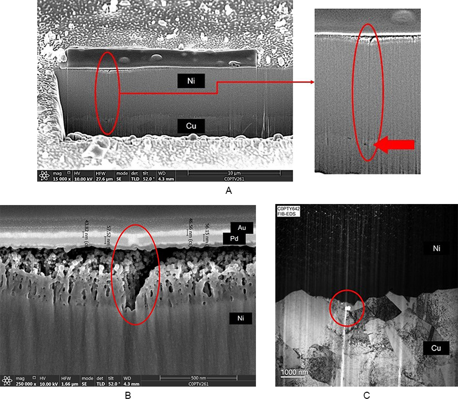
Figure 6. Nickel seam corrosion. (a) nickel seam, (b) high magnification of the nickel seam, (c) copper surface particle.
The so-called “curtain effect” occurs during FIB milling due to surface roughness and shadowing effects. This effect resembles the formation of vertical stripy, rippled patterns across the milling surface (see Figures 6a, 6b, and 6c). The curtain effect occurs during the ion attack of the milling surface and has to do with the roughening of the milling and diffusion, which smooths the surface. To minimize this issue, a protective platinum metal layer is deposited along the region of interest before the initial milling, reducing the rough surface layer and allowing the clean surface for the ion beam to mill.4
Energy-dispersive x-ray spectroscopy (EDS) was used to analyze the particle site in Figure 6c. Evidence is clear of carbon (C), oxygen (O), nickel (Ni) and phosphorous (P), along with empty space (Figure 7). The seam pathway is now set for the immersion gold to corrode the nickel deposit.
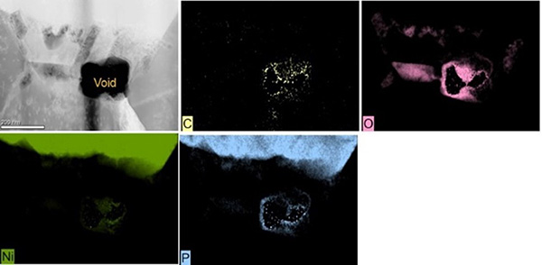
Figure 7. Nickel seam particle from Figure 6c.
RAIG Corrosion Mitigation
Conventional immersion gold electrolytes function strictly by galvanic corrosion. A mixed reaction occurs in a reduction-assisted immersion gold (RAIG) electrolyte: an initial galvanic corrosion reaction followed by an autocatalytic reaction induced by a reducing agent. This permits the RAIG electrolyte to minimize galvanic corrosion while permitting higher gold thickness capabilities than conventional immersion gold electrolytes.
RAIG electrolyte produces a uniform deposit for ENIG and ENEPIG applications with a low coefficient of variation. Wire bonding and solder joint reliability have been demonstrated to be excellent. Taking advantage of the benefits of the RAIG process enables world-class quality “on target with minimal variation.”5
Conclusions
Common electroless nickel baths for printed circuit boards typically incorporate ≤10% phosphorous, by weight, in the nickel deposit. The nickel deposit structures have hemispherical nodules that look like soap bubbles. With the electroless nickel deposit, the r/D ratio is critical and determines the cusp stresses and propensity for boundary corrosion. Electromotive force (EMF) analysis reveals nickel is approximately three times more easily displaced than palladium. If pores are in the palladium layer, the gold will preferentially exchange with the underlying nickel, causing nickel corrosion at the palladium-nickel interface. There are three primary types of corrosion with ENEPIG deposits: catastrophic horizontal, nodule pits and boundary pits. Nickel seam corrosion is a specific type of boundary pit corrosion that stems from a different origin. Process optimization through designed experiments, process management by statistical process control, and reduction-assisted immersion gold are the best ways to mitigate ENEPIG corrosion mechanisms.
References
- D-J Lee, et al., “Corrosion Behavior of Electroless Nickel/Immersion Gold Plating by Interfacial Morphology,” Electron. Mater. Lett., vol. 11, no. 4, pp. 695-701, 2015.
- G. Milad, et al., “Elimination of Nickel Corrosion in ENIG and ENEPIG by using Reduction Assisted Immersion Gold in Place of Standard Immersion Gold,” SMTA International, 2019.
- C. L. Chuang, et al., “The Effect of Nickel Oxidation Formed in the Interface of ENEPIG Structure for Flip Chip Technology,” IMAPS – 51st International Symposium on Microelectronics, Oct. 8-11, 2018.
- P. Valentine and L. Gamza, “FIB, Beyond SEM/EDS Analysis,” The PCB Magazine, February 2013.
- C. Poedtke, et al., “Next Generation Reduction Assisted Immersion Gold,” IPC Apex, Apr. 9-11, 2024.
is technical and Lean Six Sigma manager for Uyemura USA (uyemura.com); This email address is being protected from spambots. You need JavaScript enabled to view it.. He holds a doctorate in Quality Systems Management from Cambridge College, a Six Sigma Master Black Belt certification from Arizona State University, and ASQ certifications as a Six Sigma Black Belt and Reliability Engineer.


