Enabling IPX Level 7/8 PCB Waterproof Protection
Every PCB has an Achilles heel: water. Is there a solution beyond conformal coatings?
Most board enclosures are satisfactory for protecting delicate components from being damaged by accidental drops or static electricity, but provide limited protection from liquids. According to research from IDC (International Data Corp.), more than 900,000 smartphones are damaged by liquids every day globally¹.
IDC’s research revealed liquid damage is the second-largest cause of damaged smartphones (next to broken screens), with an estimated impact of nearly $100 billion each year. IDC claims by 2020, more than 1.7 billion smartphones will be shipped at a market value of $398 billion, with the problem of liquid damage only becoming more widespread if not addressed.
The need for waterproofing PCBs goes way beyond smartphones. There has been tremendous interest from producers of tablets, IoT devices, and appliances, as well as automated component manufacturers. Because of their delicate nature, electronics manufacturers are challenged to find reliable, economical and high-performance materials that minimize or mitigate the damage that compromises the safety and operation of electronic devices. Increasingly, designers want to build fluid protection into the design to improve product reliability and reduce device failures. As a result of claims by several leading mobile phone brands, consumers are now looking for water resistance and protection as a feature of new improved devices.
Until recently, thick encapsulating coatings or enclosure gasketing have been used to address the situation. Gaskets are very difficult to incorporate on devices with complex shapes (e.g., mobile phones) and take up a lot of real estate. Encapsulation eliminates the possibility of reworking a board, which creates massive yield losses during manufacturing. Due to these issues, manufacturers turned to conformal coatings, a class of surface treatments used for years to protect circuitry from foreign contaminants such as dust, flux residues, etc. These coatings were not designed to protect devices from direct contact with water, however. That level of board protection required multiple coats, a process not feasible for high-volume manufacturing. (It can take 10 or more successive applications of conformal coating.) Further complicating the process was the introduction of flex connections and press-fit connectors, as well as the use of sensitive devices such as microphones, which made masking these small electronics time-consuming and costly for traditional conformal coating applications.
Previously, water-resistant products fell into two distinct categories: conformal solution-based coatings and vacuum-deposited coatings. Both surface treatment options protected circuitry from contamination and exposure to humid environments, yet neither method was capable of achieving high levels of water protection (IPX7: full water immersion for 30 min. while powered on at 1-meter depth2,3) to electronic devices produced in mass manufacturing environments (e.g., mobile phones, tablets, e-readers, etc.).
In the ever-evolving PCB market, a “no mask” category of surface treatment emerged as a result of some recent discoveries made in research and development in the chemistry of conformal coatings. These surface treatments are capable of forming a “true” conformal coating that maintains consistent thicknesses across complex parts and provides much greater water resistance compared with traditional conformal coatings. While previous chemistries required masking of connector hubs so other parts could be electrically connected after coating, these new surface treatments are applied directly onto connectors, which prevents these points from becoming the point of failure upon water immersion. These new hydrophobic coatings are economical and can be applied inline via straightforward processes at the manufacturer. They also eliminate the need for costly capital investments and mitigate the bottlenecking batch process of vacuum-based manufacturing or masking operations.
The NanoProof 8 series is a hydrophobic coating that provides IPX8 protection and can also be applied to push-pin connectors without impeding their performance. While this treatment does not provide oleophobic properties, its ability to coat circuitry with consideration for connectors, test points, etc. is a valuable attribute.
To demonstrate the effectiveness of some of the series, several IPC-B-25A multipurpose test boards were treated with two coatings (noted herein as 7.0 and 8.4) using two different methods: rod and dip coating. IPC-B-25A multipurpose test boards were selected per recommendation from the guidelines for testing solder masks (IPC-SM-804C) and for testing conformal coatings (IPC-CC-830B). Populated devices (light-emitting diode strips) were also tested to illustrate the issues with using the industry standard conformal coating test procedures to approximate water ingress testing. This article focuses on IPX7 and IPX8 qualification of devices coated with 7 and 8.4 using rod and dip coating. Data for moisture and insulation resistance testing per IPC-TM-650 2.6.3.4A are also evaluated.
Experimental
7.0 and 8.4 were applied to general multipurpose test boards manufactured in compliance with IPC standards. The coated boards were then submerged underwater following a modified stress test of the IPX72,3 testing standard, which essentially mimics removal of the enclosure and immersion in a conductive aqueous media, making it an IPX8 level test. The boards were immersed in “Instant Ocean,”4 which was used to mimic seawater, while being forward biased for an extended period and while measuring the leakage current between the conductive paths of the comb pattern on the multipurpose test board. The test boards’ leakage current was plotted to demonstrate the overall insulation of 7.0 and 8.4, while being stress-tested in salt water. Fluctuations in current measured are attributed to either the development of minor conductive paths due to polarization of molecules in the respective coatings or due to extraneous effects on the circuit such as line noise, floating ground, etc., since the test setup was not placed inside a Faraday cage, nor was the ground circuit isolated.
In a separate test, the coatings were subject to moisture and insulation resistance testing in accordance with IPC-TM-650 2.6.3.4A, where the coatings were subject to a variety of temperatures and humidity over a period of 178 hr., as well as large biasing loads while monitoring current and insulation resistance. Similar to the modified IPX7 testing, fluctuations in current are attributed to the development of conductive paths under or through the coating, typically due to mobilization of flux residues left from soldering on the contact wires.
In a final test, the coatings were subject to the same IPX8 level test outlined previously but on live LED light strips immersed in the same saltwater over 60 min. The LEDs were assessed pre- and post-immersion testing for corrosion and functionality. This was performed as a “reality check” to compare the results observed with the IPC-B-25A boards.
Test boards. For the purposes of these tests, IPC-B-25A test boards manufactured in compliance with the IPC standards were used. The schematic is shown in FIGURE 1.
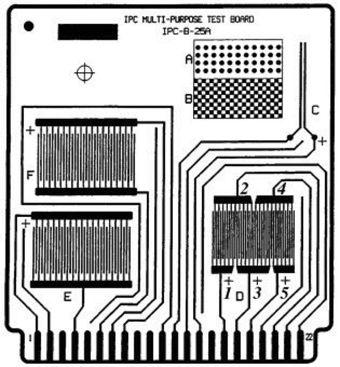
Figure 1. IPC-B-25A multipurpose test coupon schematic.
For the last test, LED light strips from Inspired LED were used to mimic a live board conducting underwater. LED strips were selected for their straightforward design and because of their visual indicators for protective properties of the coatings being tested. (Byproducts of electrochemical reactions are clearly visible on the resistors.) For the last test, some LED light strips from Inspired LED, shown in FIGURE 2, were used to mimic a live board conducting underwater.
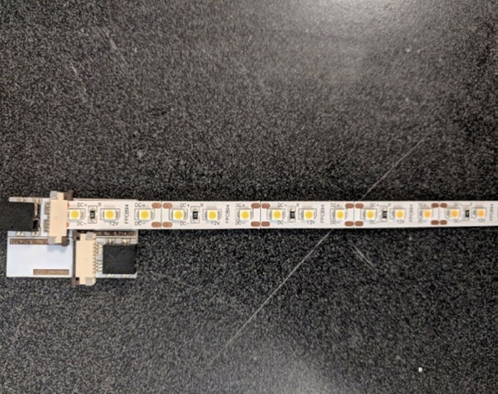
Figure 2. LED light strips.
Board preparation and coating application. The IPC-B-25A test boards were cut vertically to isolate the D and C patterns. To increase the rigor of testing, the D pattern was solely used for its narrower and condensed paths, permitting increased possibility of formation of conductive paths and parasitic capacitances between the copper traces. The test method for moisture and insulation resistance testing also required use of the D comb pattern.
Prior to testing, all boards were wiped with polyester Berkshire MicroSeal SuperSorb microfiber cloth moistened with isopropanol to clean them. Then the surfaces were blow-dried with oil-free compressed air. This preparation method removed outside contaminants such as dust, dirt and other particles, thereby eliminating coating deformities, as well as conductive pathways between the copper comb leads, which could affect conductivity, leakage current and overall results.
For application of the hydrophobic coatings, Aculon employed its recommended rod/slot coating, dip coating or dispensing. To deposit homogenous coatings, Meyer bar coating was selected for application of 7.0, and dip coating was used for application of 8.4.
To increase layer uniformity of dispensing, an R.D. Specialties RDS 50 drawn down bar was used. Once the first layer was dry, an additional layer of 7.0 was applied, and the board dried at room temperature. This ensured the final film thickness was on par with the other coatings evaluated.
To dip coat, the test board was slowly lowered into a reservoir containing 8.4 and extracted at 10cm a minute. To properly coat the board while mitigating coating defects such as bubble formation and other inconsistencies in the coating, the board was slowly inserted and extracted from the waterproofing solution. Once the board was fully extracted from the coating, it was left to hang dry in a ventilation hood at room temperature before testing. Dip coating was solely used for all treatments for the LED test.
Aculon IPX8 test method. The Aculon IPX8 test methodology was developed in adherence to the standard test method developed by the International Electrotechnical Commission, with a few modifications. The IP Code, also referred to as the Ingress Protection Rating, determines how well the given electronic device is protected from environmental hazards such as water and dust. Typically, IP ratings are given by two numbers, with the first digit referring to the solid hazards the coating protects, and the second indicates the protection level from liquids. In this test, an X served as the first digit to indicate the coating had not been evaluated for solid hazards, and the second digit an eight to indicate full liquid insertion protection to the coated IPC-B-25A board in saltwater for 60 min. at 18V bias.
The general IPX7 standard calls for an unpowered finished electronic device to be immersed in water for a period of 30 min. Following the 30 min., the device is removed and evaluated for functionality. Should the device remain functional as intended, the device meets the IPX7 classification standard. This test is typically done on fully assembled, finished electronics such as a mobile phone. This test was modified by removing the variable of the exterior casing.
This modification to the IPX7 test procedure was necessary to eliminate the varying complexities of electronic devices, to include case design, presence or absence of external ports, circuit board layering, element size, etc. Using full immersion of the IPC-B-25A boards removes variability in the enclosure type and permits direct comparison between conformal coatings on flat surfaces.
Rather than regular water, salt water with an approximate ratio of 3.8% per 39.7g per liter was used. Salt water was used to mimic harsh “real world” conditions, such as exposure to sea water, which has roughly a 3.5% salinity level, and to remove interference from the resistivity of the water and any interfering electrochemical reactions that could confound results, like the formation of insulating copper oxides.
Due to the high resistivities of the coatings, the boards were powered with 18VDC forward bias. This is referred to as Test A. In an additional separate test with newly coated boards, a 50VDC forward bias is referred to as Test B. A summary for the IPX7/8 testing is shown in TABLE 1.
Table 1. IPX7/8 Testing Summary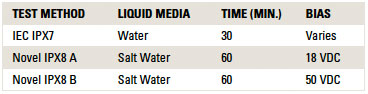
Once the test board was submerged under water, the board’s leakage current was measured using a Keithley 6487 Picoammeter over a period of 60 min. The picoammeter was programmed to gather 1800 data points, or a new data point every 2 sec., to ensure the test board was properly insulated. The Keithley 6487 also served as the power supply to directly bias the test points on the IPC-B-25A D-comb pattern.
Moisture and insulation resistance testing. Prior to the application of the hydrophobic coating for moisture and insulation resistance testing, 22 AWG wire with polytetrafluoroethylene insulation was hand-soldered onto the mounting pads of the IPC-B-25A test board using a white-water rosin flux as specified in IPC-TM-650, 2.6.3.4A. Once the wire was soldered into place, the test boards were coated as previously described. Flux residues were intentionally not removed prior to testing. Prior to testing, the boards were conditioned at 50°C for a period of 24 hr. with no additional humidity prior. Initial resistance measurements were made, and then testing began.
Once boards were fully coated and prepared, they were inserted and hung from internal racks of a temperature humidity chamber in a near vertical position. The boards were subject to 20 cycles of various temperatures and humidity, while being polarized by 50VDC along the D-comb pattern in accordance with IPC-TM-65, 2.6.3.4A. One cycle was implemented under the following conditions: The temperature was set at 25°C for the first 1.75±0.75 hr. and ramped up to 65°C. For the high phase of the cycle, the temperature was maintained at 65°C for 3.0 hr., +0.5, -0 hr., and then ramped down from 65°C to 25°C over 1.75±0.75 hr. Humidity was maintained at a minimum of 85% throughout the test until the cooldown phase, where the boards were subject to 25°C with 50% humidity for 24 hr.
To calculate resistance, current was measured with a 100VDC polarizing voltage applied to the D-pattern’s test points as outlined in IPC-TM-650, 2.6.3.4A. Five measurements were taken per test point after 60 sec. of polarizing. Current measurements were taken during the high phase of multiple cycles, rather than just the first, fourth, seventh and tenth cycles. The current measurements were taken using a Keithley 6487 picoammeter, along with the 100VDC polarizing voltage. The general 50VDC biasing maintained throughout the test was provided by a Jameco 50VDC power supply.
Table 2. Test A Results (18 VDC Bias)
Test Results
Aculon IPX8. The general IPX7 immersion testing standards call for the immersion of finished devices in regular water for 30 minutes. After immersion, the finished electronic device was evaluated for functionality. The Aculon IPX8 modified testing was more strenuous in that an exposed board was being directly submerged and polarized in salt water with 18V of direct current over a period of 60 min. To further stress the insulation, the test was rerun at 50VDC with newly coated boards following the same manner previously described.
As illustrated in FIGURE 3A, it is apparent an exposed, uncoated test board was severely damaged if powered up while immersed in salt water. The current ranges around 2.5mA were internally limited to 2.5mA to protect the ammeter.
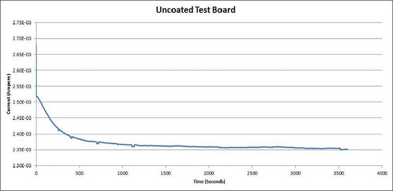
Figure 3a. Uncoated test board results (18VDC bias).
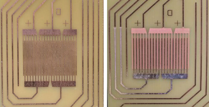
Figure 3b. Uncoated before immersion vs. uncoated post immersion.
Upon closer inspection of the boards, it was evident the board had become extremely corroded post-immersion. After coating with the hydrophobic chemistries, the results are completely different. The results of 7.0 and 8.4 are outlined in FIGURE 4A.
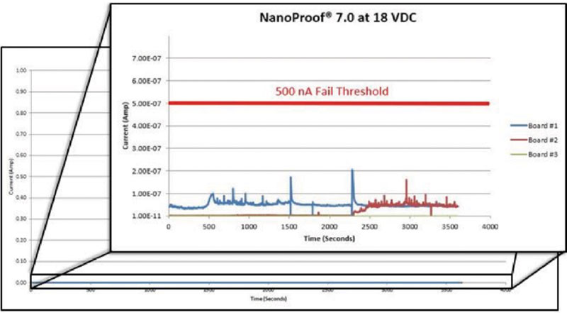
Figure 4a. Results of novel chemistry 7.0 at 18VDC.
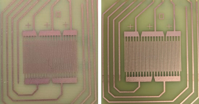
Figure 4b. Novel chemistry v. 7.0 pretest (left) vs. post-test.
As indicated by Figure 4A, on average, current did not exceed 100nA. Test board 1 and 2 spiked over 100nA, most likely due to line noise or interference from other electrical equipment the picoammeter is detecting as a result of the scale at which the current is measured. In general, the safety standards for electrical devices such as handheld devices can leak on a larger scale (up to 250µA allowed) than the current being detected5. The development of negative currents can be attributed to line noise due to the scale at which current is being measured. Since the boards have such low leakage currents, ion migration is minimal, and the coating provides a high amount of insulation.
On average, the amount of insulation resistance for 7.0 applied in this manner is in the gigaohm range, as seen in TABLE 3. Compared to an uncoated IPC board, the leakage current has been scaled down by a factor of nearly 100,000. Even at its highest amount of leakage per Table 3, 204nA, and the lowest amount of leakage for the uncoated board per Figure 3A, around 2mA, the amount of current leakage is still lowered by a factor of 10,000 for 7.0 when applied in this manner.
Table 3. Summary of Electrical Data for Test A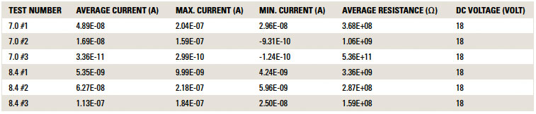
Table 4. Summary of Electrical Data at 50VDC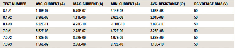
In the case of 8.4, the current did not exceed 250nA. Indicating on average 8.4 applied in this manner provides around a gigaohm range of insulation. All these leakage rates are exponentially smaller than that of an uncoated board, as indicated in Figure 2A. There is a decrease in leakage current by a factor of 40,000 on average for 8.4, and compared with the lowest leakage rate for the uncoated board and the highest leakage rate of one of the 8.4 boards, the decrease is still by a factor of 10,000.
The hydrophobic coatings were compared with two traditional, notable conformal coatings under electrical testing, one acrylic-based and one polyurethane-based. As evidenced from the data in FIGURE 5, all four coatings exhibited the same performance on the IPC-B-25A test boards. Spikes in the data were attributed to line noise detection, as well as potential coating defects like pinholes.
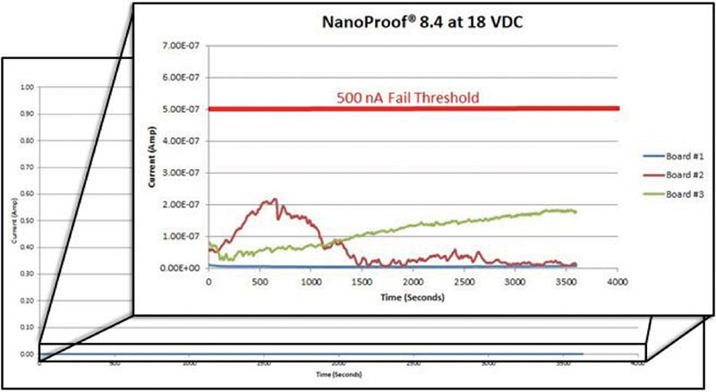
Figure 5A. Results of novel chemistry 8.4 at 18VDC.
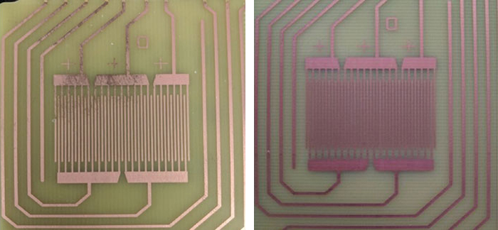
Figure 5B. Novel chemistry 8.4 pretest (left) vs. post-test.
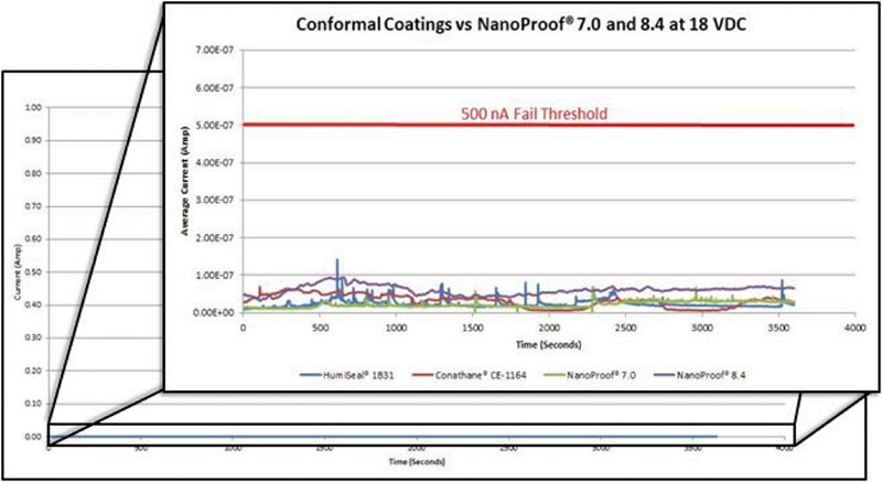
Figure 5c. Average current vs. time for two conformal coatings vs. novel chemistries 7.0 and 8.4.
Test B. The standard Aculon IPX8 modified test calls for the IPC-B-25A board to be polarized with 18V. To demonstrate the insulation properties provided by 7.0 and 8.4, the boards were also biased with 50VDC. The data are shown in FIGURE 6. Again, all four coatings performed well, even at high bias, indicating they can all adequately protect 2-D circuitry.
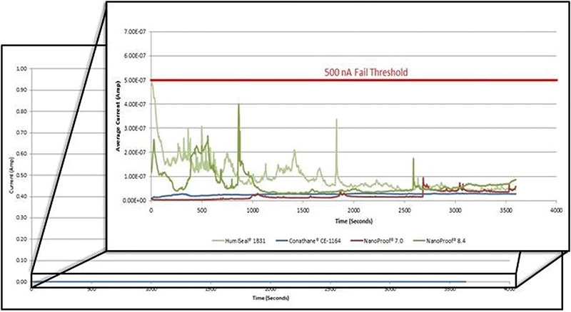
Figure 6. Conformal coatings vs. 7.0 and 8.4 at 50VDC.
Moisture and insulation resistance. The criteria for passing moisture and insulation resistance as specified in IPC-CC-830 is for the test points of the D-comb pattern to remain greater than 500MΩ or 5E+8Ω. 7.0 and 8.4 results are outlined in TABLE 5 and TABLE 6.
Table 5. Summary of Average Resistance per Test Points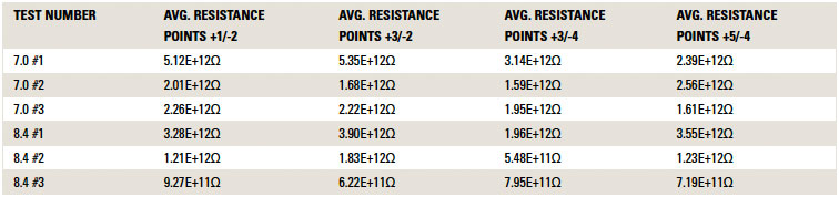
Table 6. Summary of Average Resistance per Time Interval Measured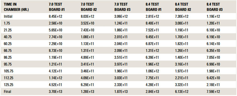
Also indicated in Tables 5 and 6, 7.0 and 8.4 exceed the criteria for moisture and insulation resistance. Moisture and insulation resistance testing is designed to stress the applied coating through exposure to various temperatures and humidities. Any contaminants present on the board or in/on the coating may react with water over time and form conductive traces. The polyurethane and acrylic coatings have resistance values of 1.3E+10 and 6E+10 after MIR testing, respectively (values as reported by the manufacturers), which are similar to the aforementioned values for 7.0 and 8.4. This indicates all the coatings are appropriate for insulation of conductive surfaces.
IPX8 functional board. The IPC-B-25A test board is a well-regarded process qualification vehicle to test coatings, but the complexities of printed circuit boards vary in element size, design and purpose. As a true functional test, some flexible LED strips were coated and performed a very similar test to the Aculon IPX8 test, but the strips were powered with 12VDC, rather than 18VDC. The deviation was due to the inherent design of the strips. The circuitry was still immersed in the same “Instant Ocean” salt water mix for 60 min. and evaluated for corrosion/functionality post-testing. Results are illustrated in FIGURES 7a through 7e.
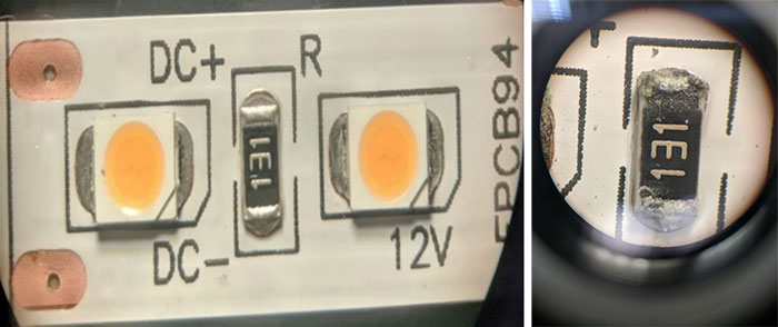
Figure 7a. Uncoated LED strip pre-immersion (left) vs. post-immersion (corrosion visible).
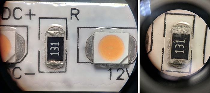
Figure 7b. Polyurethane conformally coated LED strip pre-immersion vs. post-immersion (corrosion visible).
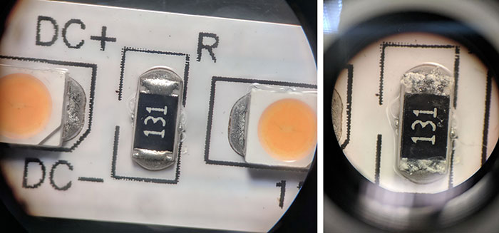
Figure 7c. Acrylic conformally coated LED strip pre-immersion vs. post-immersion (corrosion visible).
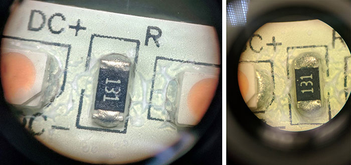
Figure 7d. 7.0-coated LED board pre-immersion vs. post-immersion (no corrosion visible).
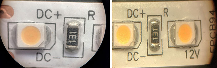
Figure 7e. 8.4-coated LED board pre-immersion vs. post-immersion (no corrosion visible).
From IPX8 testing data on the IPC-25A boards, it could be surmised all four coatings would have performed similarly with insulating materials providing adequate protection from water damage. Further examination of the LED boards after 60 min. immersion in salt water indicated the uncoated strip and the acrylic and polyurethane coated strips still developed corrosion, whereas boards coated with 7.0 and 8.4 showed none. Although the traditional conformal coatings have very high resistivities and excellent MIR performance, they rapidly fail water immersion testing on a test part with a 3-D structure. While this may seem counterintuitive, note the former conformal coatings were not designed to provide IPX7 protection. Rather, they were intended to protect circuitry from corrosion, current leakage and component damage due to contaminants present on the board or those present in their operating environment. So, while the traditional conformal coating chemistries have excellent insulating properties, they are not capable of achieving the desired level of thickness required for direct contact with liquid water without multiple successive applications, a process not feasible for volume manufacturing. In contrast, the 7 and 8 series chemistries were specifically designed to be deposited in volume production with a single coating pass being sufficient to pass IPX7 and above. 8.4 also has an added benefit of being able to coat connectors without loss of continuity.
Summary and Conclusions
Superficially, indicators show 2-D test circuity of the four tested coatings (acrylic, polyurethane, 7.0 and 8.4) would demonstrate similar circuit protection from water. However, when actual functional 3-D circuitry devices were tested with acrylic and polyurethane coatings, they exhibited corrosion and device failure in under 60 min. of saltwater immersion testing. The devices coated with 7.0 and 8.4 did not. The hydrophonic series of coating chemistries create an insulation barrier for electronics, protecting them from liquid media such as water and prevent liquid-induced damage during operation.
In today’s competitive marketplace where the value of electronic devices, particularly smartphones, is constantly rising, with the risk of water damage rising concurrently, not having some kind of water resistance to the device is becoming a serious problem for device designers/manufacturers. Application of the latest generation of hydro/oleophobic coatings provides longevity to devices under real-use circumstances when exposed to liquids.
However, application of the latest generation of hydro/oleophobic coatings can help these devices achieve longer lifetimes under real-use circumstances, where they will be subject to exposure to liquids.
References
1. Francisco Jeronimo, “A Problem with Mobile Phones that is No Longer Acceptable (Part I),” December 2016.
2. The IP Code is a test standard published by the International Electrotechnical Commission (IEC) and describes the level of protection provided by an enclosure. For an explanation of the IP code see ce-mag.com/archive/06/ARG/bisenius.htm.
3. IP code defined, engineeringtoolbox.com/ip-ingress-protection-d_452.html.
4. Sea salt information, instantocean.com.
5. Leakage Currents in Modern Technology, marcspages.co.uk/pq/3333.html.
is engineer, , is vice president of technology and Edward Hughes is CEO of Aculon (aculon.com); This email address is being protected from spambots. You need JavaScript enabled to view it..


