Some Smoothing on a Noisy Topic
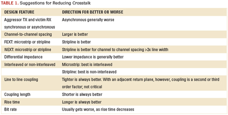
Suggestions for reducing crosstalk.
At least four significant problems contribute to eye collapse and an increased bit error rate in high-speed serial links. Our previous two columns addressed how reflections and losses affect ISI, collapse of the eye, increased deterministic jitter and higher bit error rates. This month we look at how channel-to-channel crosstalk contributes to ISI and collapse of the eye.
Crosstalk from one channel to another can range from as high as 20% in some cases to as low as 0.01% in other cases. And just how much is too much, of course, depends on the received signal strength and how much noise margin is needed at the receiver. In an extreme case, the received signal may be as low as -30 dB from the transmitted signal and still acceptable. If a signal-to-noise ratio of at least 10 dB is desired, then the crosstalk should be less than -40 dB. This is less than 1%.
This is the basis of a simple rule of thumb. Unless you have an extreme channel, the channel-to-channel crosstalk should be kept below -40 dB. If it is ever larger than -40 dB, it may be important to perform analysis to see how much you can tolerate in your specific design.
One reason crosstalk discussions in the literature are so confusing is that so many design factors influence the magnitude of crosstalk. One could easily imagine a situation when it is a killer problem and other cases when it is trivial. It all depends on the specific design conditions and the criterion of how much is too much.
For example, consider a very bad, pathological situation, as illustrated in FIGURE 1. Two differential channels are routed in long lines in FR-4, but isolated from each other. However, there is a connector or package with 2" of trace in microstrip. Although it is designed as a 100Ω differential impedance, all four signal lines are tightly coupled with a spacing equal to their line width. This occurs very often in flex connector strips.
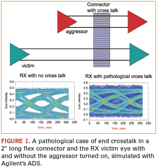
With a rise time of 25 psec, typical of a high-end PCIe gen II part, and a coupled length of 2", the FEXT would be about 20%. In this pathological configuration, the far-end noise is generated close to the aggressor TX, so the rise time is the shortest, and the FEXT noise travels to the victim RX very close to the connector, so it suffers little attenuation.
The poor victim RX is at the end of a long, lossy interconnect, so the received signal is attenuated. If the two channels are asynchronous, the noise on the victim line is uncorrelated with the received bit, so the noise will spread uniformly over the entire unit interval.
This 20% FEXT noise, spread over the unit interval, can completely close a marginally acceptable eye, as in Figure 1. In some cases, channel-to-channel crosstalk can ruin your day, and it can arise in board traces, via stacks, connectors, packages and cables.
What can you do to reduce crosstalk to an acceptable level? TABLE 1 contains some suggestions. But, remember, you have to do your own analysis.
Ph.D. is a signal integrity evangelist with Bogatin Enterprises, a LeCroy Co. He is giving two talks (one free) at PCB West (pcbwest.com) in September.
Register now for PCB West, the leading conference and exhibition for printed circuit board design! Coming Sept. 9-12 to the Santa Clara Convention Center. pcbwest.com


