Over-Molding Plastic over Flex Circuits
It can be done, but there’s always a learning curve.
Question: I have an application for a wearable device. I would like to encapsulate the flexible circuit in plastic. Is it possible to over-mold plastic over a flex circuit? If so, are there special design considerations I would need to incorporate?
Answer: The response is way too much to cover in my allotted space, so it will have to be a “two-parter.” Here goes for part 1!
Yes, you can over-mold plastic over a flexible circuit, but multiple factors have to be in alignment for the application to function as intended. These factors are:
- Flex circuit design (conductor routing and material stackup).
- Final configuration (Will the final form factor support the intended application?).
- Mold design.
- Molding material.
- Molding procedures.
If even one of these factors is off, the result will be the inability to successfully over-mold the flex, or premature failure of the flex after over-molding. Expect a learning curve. The first attempt may not be what was expected, and some tweaks to the design or molding process will probably be necessary to build a successful end-product. I will cover each of the critical factors individually.
Flexible circuit design. Let's assume that since the application is a wearable device, the function is dynamic, and the flex subject to hundreds or thousands of bending cycles. This means the flex circuit needs to be designed using dynamic flexing guidelines. I could spend an entire article on this subject alone because it may well be the single most important feature of the overall success of the finished assembly. I do a lot of preaching in my professional development courses about the effect of the neutral bend access location on a bending flex circuit. The location of the neutral bend access is equally important in an over-molded design, but now you also have to factor in the plastic material. Since the plastic will be bonded to the flex, the entire over-molded assembly will behave more like a single piece of material, with the flex just one component that impacts how it behaves when bent. If the flex is skewed significantly toward the inside or outside of the overall neutral bend axis, it will be exposed to extreme tension or compression forces. These forces can significantly reduce the number of bending cycles before failure. You may want to consider specific “hinge” areas that will do all the bending. The flex circuit should track straight through these areas (in the x-y axis when viewing from the top surface of flex), and these areas should be kept free of components or other discontinuities. Any discontinuity could cause a stress concentration point when the over-molded assembly is bent, and this could damage the flex. Design the flex so all conductors in flexing areas have no plated copper (not even a flash) on the surface. This may require adding additional layers so flexing conductors can be buried on layers in the middle of the stack that do not get plated (assuming all plated through-hole and/or blind vias from outerlayers connect to the adjacent layer only). If using HDI construction with sequential drilling, plating and lamination processes, this may not be possible. Keep in mind that having copper-plated internal layers will significantly limit flex performance.
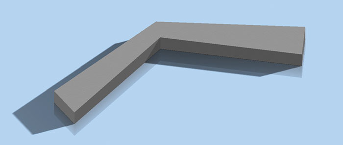
Final configuration. You now need to ask yourself, “Will the shape and construction of the final product support what I want it to do?” A customer recently sent me a competitor’s failed flex for analysis. This flex had been over-molded into a plastic that was so hard that it felt almost brittle. The final configuration was an elongated “V” shape where the two legs tapered in width, and the inside of the “knee” had a very sharp corner (FIGURE 1). That area was not intended to bend, but it did – just a little. Because the legs were tapered, and the inside angle was a sharp corner, coupled with an extremely hard plastic molding, an almost invisible crack formed. The crack propagated to the flex and caused a couple conductors to crack as well. The hard plastic forced the flex to stretch in this area. It did not provide stress-absorbing relief. So it turned out it wasn’t the other flex vendor’s product that was defective. It was the configuration of the final product (i.e., design fail). Had the final configuration been more like FIGURE 2, the miniscule crack in the plastic that ultimately caused the failure would probably never have formed.

Figure 1. The very sharp transition in the molding material caused an almost invisible crack, which propagated to the flex, causing several conductors to crack.

Figure 2. Had the overmold been configured as shown above, the cracks probably would not have formed in the plastic.
Part 2 of this article will cover mold design, molding materials and procedures, and miscellaneous concerns.
is senior application engineer at Flexible Circuit Technologies (flexiblecircuit.com); This email address is being protected from spambots. You need JavaScript enabled to view it.. He and co-“Flexpert” Nick Koop (This email address is being protected from spambots. You need JavaScript enabled to view it.) welcome your suggestions.


