The Hot Zone
For thermal management, how does FPC compare to rigid material?
Mobile devices are a modern computing marvel. What once filled an entire room now fits in a shirt pocket and is an indispensable convenience, with enough processing power to browse the Internet, send/receive email, watch a movie, listen to a favorite song, provide location guidance, and even (on a rare occasion) make a call. Computers in your pocket: Who would have believed it 20 years ago, when a PC needed a sturdy desk and a huge noisy fan to keep the processor cool?
The size may have changed dramatically, but heat management issues remain the same. Indeed, they may be exacerbated in that the device form factor does not permit an integrated fan to cool the device. There are common techniques to manage heat within a device applicable to both rigid and flexible printed circuits, such as adding a metal heatsink on the components, thermal vias to transfer heat from the component side of the board to the opposite side, and thermal grease to facilitate heat transfer from the board to an external frame. But what about the boards themselves? Are there significant differences in thermal management
between FPC and rigid?
Today’s mobile devices have no room for heatsinks on computers, no room for airflow between components, and no designing out of high-performance components that generate large amounts of heat. What we are left with is a thin, highly-populated device that generates heat that needs to be distributed over large areas to eliminate “hot spots” that are discomforting to users and detrimental to device performance. How do ultra-thin devices manage this heat, and how are FPCs used to accomplish this? Does the migration to FPC come at the cost of thermal management? Let’s take a look at the differences in thermal conductivity between FPC and rigid PCB materials.
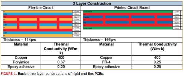
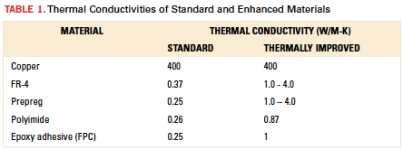
Figure 1 shows the two basic constructions using standard FPC and rigid PCB materials. Comparing material properties of the two constructions created using standard materials reveals very similar properties between the two sets of materials. Thermal management is critical to device performance. As such, materials have been modified over the years to manage the thermal output of high-performance components. Adjusted thermal conductivities for premium materials are shown in Table 1.
[Ed.: To enlarge the figure, right-click on it, then click View Image, then left-click on the figure.]


The increase in thermal conductivity is relatively small, especially in FPC materials. Given the disparity in material properties, what advantages does an FPC have over rigid? Given the lower thermal conductivity, two attributes contribute to the success of thermal management when using an FPC. First, the very thin materials permit a short, efficient path away from heat-generating components. The second is the ability to form the circuit, enabling intimate contact with heat spreaders such as frames, housings and metal stiffeners.
Let’s take a look at how some of these thermal management techniques are implemented. First, we will look at adding areas of metal to the circuit. This can be adding metal to the entire area of the circuit or only in localized areas where heat is generated. The two aspects of this are incorporating the metal into the laminate and laminating metal to the circuit.
As a metal core laminate, the polyimide is cast or laminated directly to a sheet of metal, typically aluminum. The aluminum can be on one side of the laminate or sandwiched in between two polyimide layers (single copper layer board, double copper layer board). A typical application is LED lighting.

The advantages include the availability of various metal thicknesses, and the rigidized substrate, which facilitates circuit fabrication, and which facilitates mounting of the circuit through screws/bolts or clips.
The disadvantages include board thickness and weight. Also, the aluminum backer can make processing difficult, as it is not compatible with all standard FPC/PCB wet chemistries. Finally, it is difficult to mill complicated outline shapes.
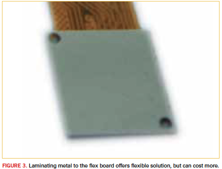
The second path to a metal backed circuit is to laminate metal to the finished FPC (Figure 3), a common practice within mobile devices. This method permits a highly customized board.

Advantages include multiple metal thickness can be placed on the same circuit; different types of metal can be placed on the same circuit; and unique metal shapes can be laminated to the circuit that do not have to match the circuit outline, recessed or overhang. Finally, metalized areas can be used as a robust circuit mounting location.
Disadvantages include higher manufacturing costs brought about by laminating the individual metal backer to a circuit; the unevenness of the circuit board thickness adds complexity to the assembly tooling; and a thin flex circuit with localized heavy sections due to metal backers adds complexity to circuit handling to prevent tearing.
Second is the use of thermally conductive adhesive to mount the FPC to external frames or housing. Typically used to mount metal heatsinks to components, this adhesive can be applied to the flex circuit by the manufacturer prior to shipment to be used as a thermally conductive mounting tape. Typically it is a pressure-sensitive adhesive type (PSA), but thermal set adhesives are available also. Such tapes can be processed with a variety of techniques to produce unique shapes and attachment methods. The tapes can be used very effectively with thin flex circuits with or without thermal vias to act as an interface to remove heat from the circuit.
The advantages of the tapes are they are easily processed into unique shapes; they come in a range of thicknesses from five to 20 mils; they can be placed within the circuit outline; and they can be used as an interface between uneven surfaces.
The disadvantages are they add a substantial thickness increase (minimum 5 mils) to the board thickness; and as with all PSA materials, they have a tendency to creep and may not have sufficient bond strength to adhere to very small areas. Finally, they can be quite expensive as material thickness increases.
Last is use of thermal management films. These films are designed to spread heat away from localized hot spots to prevent damage to surrounding components and remove hot spots from a device that can cause discomfort to the device user. The advantages include thicknesses down to 50µm, up to 1500 W/m-K thermal conductivity, a degree of flexibility, and customizable shapes. The disadvantages are relatively poor Z direction thermal transfer, a lack of suitability for tight bend radius, and a material cost much more expensive compared to stainless steel.
Flex circuit materials may not have thermal conductivity values as high as those of FR-4 or prepreg, but that does not mean they are not a good choice for circuits when thermal management has a high priority. Combining the properties of thinness and flexibility with thermal conductivity, a design can be selected that meets thermal management needs.
Dale Wesselmann is a product marketing manager at MFLEX (mflex.com); This email address is being protected from spambots. You need JavaScript enabled to view it.. His column runs bimonthly.


