Design for Rigid-Flex
 Rigid-flex circuits combine the best of both worlds.
As product designers run out of printed circuit board (PCB) real estate in the x-and y-axis, they look to the z-axis and stacking technologies to solve their problems. Current solutions include board-to-board connectors, polyimide-based flexible (flex) circuits, polyimide-based, rigid-flex circuits and cabled interconnections. Board-to-board connectors are the most common method of 3D stacking due to pricing and a myriad choice of solutions based on size, density, industry standards and signal integrity (SI) issues. While the board-to-board interconnect choices are seemingly endless, they compound the initial problem they attempt to solve by consuming valuable PCB real estate. Additionally, the daughter card assembly is required to contain the mating half of the connector set, again using up valuable real estate.
Polymide flex circuits. Polyimide-based flex circuits offer a connectorless interconnect solution. The 3D solutions are endless and offer the most creative freedom to packaging designers. Flex circuits technology enjoys strong popularity in certain market and according to the latest market intelligence, is well over $5 billion and still growing. The technology allows for static (bend-to-flex) and dynamic applications whether it is one or hundreds of thousands of cycles. Flex technology allows multiple boards to be combined into one PCB, yielding a single part number, bill of materials (BOM), stencil, assembly operation and testing prior to folding into the final configuration, but this comes with a price. There are a limited number of suppliers with higher materials costs, elaborate tooling, longer lead times and lower yields. Typical per piece pricing can be three to four times that of FR-4 based rigid PCBs.
Rigid-flex circuits. Rigid-flex circuits combine the best of both worlds, providing a rigid portion for component and mechanical mounting and a flexible portion for transitioning signals from one surface to another in either a static or dynamic application. Unfortunately, they suffer from the same drawbacks as flexible circuits – limited suppliers, higher material costs, elaborate tooling and longer lead times with lower yields. In addition, materials mismatched between FR-4 and polyimide further increase the difficulty in successfully combining these circuits. This is reflected in a similar three- to four- time price modifier vs. rigid boards. This can be modified in the “static” flex applications with the use of “flexible FR-4.” But again, the supplier base for this “patented” application is even further reduced.
Cabled interconnections are the lowest technology solution for 3D problems. They offer maximum design flexibility, are simple to build, offer unlimited length and quick-turn capability but are manually intensive, difficult to rework and offer limited SI solutions.
Those familiar with rigid PCB manufacturing know that raw, thin core materials are very flexible right out of the package. It is this flex portion that requires the design attention. In this section, the use of plated through holes (PTHs) is discouraged and the transition region requires the use of rounded angles and not sharp bends. A great guide for design can be found in Joe Fjelstad’s free book, “Flexible Circuit Technology-3rd Edition”1. Many of the design constraints are explained by the manufacturing process.
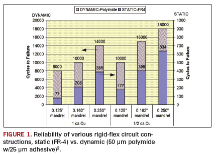
Design and fabrication are the first pieces of the puzzle, but for market acceptance, the final product needs to be thoroughly tested to accepted industry standards – in this case, IPC-TM-650 9 (see FIGURE 1). This testing requires that the flexible substrate be repeatedly folded over a mandrel, a metal rod of specified diameter, until failure. The static application using the flexible FR-4 shows reliability with 77-634 lifetime flexures, normally exceeding the requirements of most static applications.
 R
R
igid-flex applications are one of the most appealing 3D interconnect architectures. The innovative use of new materials is making these applications more cost competitive to the conventional board-to-connector structures. By using existing rigid PCB manufacturing processes and technologies, with a couple of new twists, fabricators are now able to provide a solution that saves customers 30% to 70% of their current per piece costs.
References
1. Joseph Fjelstad, Flexible Circuit Technology, 3rd edition. January 2009. http://hdihandbook.com
2. Shawn Arnold, “Flexible FR-4: A Low-cost Replacement for Polyimide-based Circuits,” CircuiTree, June 2004.
Happy Holden is a recently retired senior technology specialist for Mentor Graphics.


