Advanced Registration Systems
An integrated registration control system can provide feedback for continuous improvement, increasing overall process yields.
Whether we operate in boom times or an economic downturn, improving yield remains the major challenge for all PCB companies. In the good times, higher yield means higher capacity, shorter lead times, improved factory utilization and better profits. In the not-so-good times, it means all of the above plus something much more important: survival.
For most engineering managers the scrap pareto will be one of their vital business tools, helping to identify the causes of product failure thus driving improvement. It is a fair bet that you could take a scrap pareto from any shop globally and see the same top five categories – though not necessarily in the same order. It is also a near certainty that “registration” would be included within that top five. However, while a category like “innerlayer opens” can generally be identified in one or two process areas (AOI and E-Test), “registration” is often used as more of an umbrella term with its pernicious effects seen in a number of process areas.
The greatest proportion of registration scrap results from having applied incorrect innerlayer scale factors at CAM. The impact of this is costly in technical, commercial and resource terms. The ability to get innerlayer scale factors right the first time at CAM is essential for all manufacturers of multilayer PCBs, and especially those in the quick-turn business.
In principle, the correct scale factors to apply at CAM are determinable as a function of material and process influences. The following factors should be considered.
- The materials used in the stackup
- Vendor and resin system
- Core structure (glass construction, etc.)
- Copper weight and copper distribution (signal, mix, plane, etc.)
- Prepregs used (quantity, glass style, resin content, etc.)
- Press cycle and Process influences
- Grain/Fill (warp/weft) influence
- Other factors
- Effect of adjacent cores, position of the core in the stack, mass lamination vs. pin lamination
- Effect of adjacent cores, position of the core in the stack, mass lamination vs. pin lamination
However, as anyone who has had responsibility for the lamination department in more than one PCB shop will testify, scale factors that are good for a specific set of materials in one shop will likely not be good in another shop. For instance, the influence of the shop’s specific processes – particularly the press cycle – are critically important.
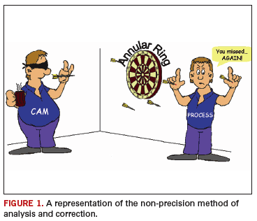
Being able to predict scale factors correctly at CAM is generally achieved by one of the following four methods: individual experience, a data-driven intelligent system, god-like powers of intuition or luck. In practice, however, individual experience relies heavily on both god-like powers of intuition and luck, and it is unlikely to be a method of choice. Taking a manual approach to a data-driven system will probably ensure that the responsible engineer is further challenged by sorting through masses of machine, CAM and process data to try to identify the influence of material and process on scale factors and registration yield. Naturally, having the right tools for analysis and correction are essential. FIGURE 1 gives a representation of the non-precision methods.
Knowledge Makes the Difference
A quick definition: Data are facts that are the result of observation or measurement. Information is meaningful data or data arranged or interpreted in a way to provide meaning. Knowledge is internalized or understood information that can be used to make decisions.1
In our industry, it is not a lack of data that limits making intelligent decisions about scale factor, on the contrary. With modern CAM systems and process hardware, PCB manufacturers could perhaps rightly complain that they have access to more data than they handle. Instead, what is required is a system that allows rapid, automated interpretation of complex data taken from key process step(s) in your facility and then converts this information into real-time reactive registration improvement – while providing the knowledge to drive accurate CAM prediction. Ideally, the system should use an automated visual approach to streamline data from multiple sources and display it in a uniform manner.
In any business cycle, but particularly in a negative economic climate, there should be two key criteria for any system: the system itself should provide rapid ROI and the system should maximize investment in existing capital and resource. Therefore, a good starting point is to have the system interface to equipment and systems that are currently available.
By implementing an integrated system that can gather data from existing hardware and CAM systems, one can drive a step change in registration yield by using a powerful self learning model. The system provides accurate prediction of scale factor at CAM and essential reactive analysis to maximise yield of products in manufacturing.
In TABLE 1, we look briefly at some of the manufacturing process from Pre-CAM through to drilling and identify where we can collect useful information that could drive an intelligent model.
Recall that we are speaking of data that can drive a predictive model of PCB scale factors to be applied at CAM. Therefore, measurement needs to incorporate the layer-by-layer distortion during the lamination process and all prior processes.
X Ray Drillers, X Ray CMMs or Intelligent Drill Systems (referred to as “optimizers” in the following text) are the only equipment in the above list that can provide scale data for every layer in the stack after lamination – the point when the sum of material and process variations in the prior processes can be determined. It should be noted that some advanced laser drill systems are able to provide compatible data for the model, but the primary machine interface for most users remains the optimizer.
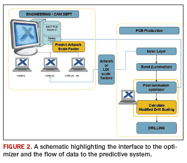
A schematic of the system is shown in FIGURE 2 highlighting the interface to the optimizer and the flow of data to the predictive system.
Many modern optimizer systems are capable of quickly analyzing the individual scale factors in both panel axes (grain-and-fill or warp-and-weft directions) simultaneously on every layer making for rapid and accurate analysis. Advanced systems are additionally able to analyze non-linear distortion by measuring targets around the periphery of the panel providing an even greater level of understanding of material distortion.
Of course, optimizer capacity is finite, and it will be reduced when measuring each and every layer; however, it is not necessary to measure every panel in this manner. It is perfectly adequate to measure the majority of panels in the lot with standard overlapped targets and use “every layer” measurement for a smaller sample – often 5% to 10%. When product technology increases or factory-loading levels are reduced, and manning allows, it is beneficial to increase the sample size to enhance the collection of information.
- The self-learning model then combines the following elements of information:
- Detailed knowledge of the stackup and materials used – directly from CAM/PreCAM
- Applied scale factors on each of the inner layers (artworks / LDI) – directly from CAM
- Measured scale error on each internal copper layer post lamination – direct machine link
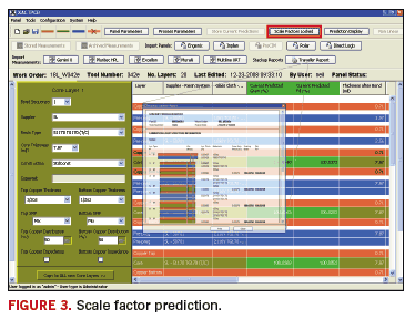
Using this information, it is possible to use advanced mathematical methods to “parameterize the stackup” to break the stackup down into discrete material and interaction elements that influence the scale factor. The parameters are then determined by analysis of the layer-by-layer scale error occurring after lamination. By continuously feeding the model with stackup and associated machine data, the model attains increasing prediction accuracy. Another benefit of such a system is that scale factor prediction (shown in FIGURE 3) is always up to date and current – using the most recently captured data for scale factor prediction to identify and take into account the effect of variation in material supply.
In addition to feeding the self-learning model, the ability to analyze scale errors after lamination but before drilling allows for small compensations to be made to the drill program. We refer to this as reactive scale factor improvement.
A GUI (graphic user interface) seen in FIGURE 4 allows operators, engineers and line managers to independently log in to view and to analyze data from any product lot – either in real time for drill compensation or for later analysis such as publishing a non-destructively generated “registration Certificate of Conformance” for supply to the end customer. In contrast to a standard microsection-based registration report, where the sectioned panel is sure to be a scrap circuit, this method can be guaranteed to be based on one or more of the circuits (panels) shipped to the customer.
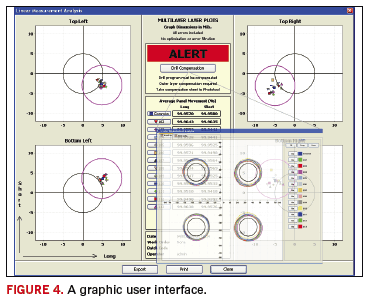
The reactive improvement system automatically compares the scale error on the measured panels against the available annular ring and drills to copper design rules. Where product is found to be out of tolerance or registration can be further improved, compensation algorithms automatically calculate a best-fit scaling that can be applied to the subsequent drilling process. Such compensation factors can be fed automatically to Drill/CAM eliminating errors caused by manual calculations and subjectivity.
The system is compatible with the leading optimizer systems and providing that the machines are networked – the system can easily access and process data from multiple machine types. In this way, a facility that has more than one type of post lamination optimizer will benefit from a common graphical user interface to their data.
Benefits of an integrated registration control system include a cycle of continuous improvement that can:
- Predict – Scale factors predicted at CAM
- Measure – Post lamination optimizer
- Optimize – Reactive optimization to improve batch yield immediately and feedback scale errors to the Prediction Engine for further-improved prediction accuracy
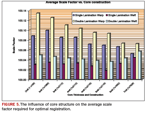
This leads to the key benefits: knowledge and understanding of the material and process factors that influence and control registration. The chart illustrated in FIGURE 5 is based on data accumulated from a number of different PCB facilities and demonstrates the influence of core structure on the average scale factor required for optimal registration.
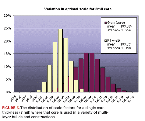
Of course, the optimal scale factor for each given core depends on many other factors. FIGURE 6 shows the distribution of scale factors for a single core thickness (3 mil) where that core is used in a variety of multilayer builds and constructions.
Conclusion
The measure of success for a registration prediction and control system is that it should: interface with existing equipment and data streams; close the loop between CAD and process; improve yields; reduce lead time and improve throughput; and, of course, improve profit.
A long-term user of this system determined within a few months of use that it no longer required first article lots because the predicted CAM scale factors proved to be right the first time. This enabled new PCB designs to be committed straight to production – significantly reducing lead-time and costs. PCD&F
REFERENCES
1. Prof C. Tenopir, University of Tennessee, USA (quoted at www.success.co.il/is/dik.html).
Neil Chilton is sales and marketing director at XACT PCB Limited and can be reached at This email address is being protected from spambots. You need JavaScript enabled to view it..


